LanguageTool: Powerful Language Checking on Your Own Network
LanguageTool is one of the leading open-source solutions for grammatical and stylistic text checking. While most users are likely familiar with the cloud-based version, the on-premise (self-hosted) variant is gaining increasing importance – especially for businesses, educational institutions, and organizations with high data protection and control requirements.
The core of LanguageTool is licensed under the GNU Lesser General Public License (LGPL-2.1). This license permits the free use, modification, and distribution of the software, even in commercial environments, provided that changes to the original code are also published under the LGPL. The license is “weak copyleft,” meaning that applications using LanguageTool as a library do not necessarily have to be open source. License information can be found in the official repository on GitHub in COPYING.txt. Third-party components such as dictionaries may be under different licenses (e.g., GPL).
There is an open-source version as well as an extended premium version with additional features such as improved style, semantics, and format checks. A detailed overview can be found on the website. It is important to note that for self-hosted instances, premium features are only available for commercial use and by individual quote. However, this is communicated with difficulty and primarily in the forum upon request. It also appears that not all premium features are available.
Unfortunately, LanguageTool made changes to the use of browser extensions in 2026: a premium subscription is now required for cloud usage. The self-hosted version remains unaffected – here, the browser extension can still be connected to your own server to enable seamless integration into web applications such as email, CMS, or forms.
Features
LanguageTool has a modular design and combines several technologies. These go far beyond the integrated spell checking of, for example, LibreOffice or Thunderbird. However, a much-desired feature is currently not yet available: support for multiple languages within a single document.
-
Morphological Analyzer & POS Tagger
First, the text is broken down into sentences and words. Each word receives at least one Part-of-Speech (POS) tag (e.g., noun, verb, adjective). The analyzer also considers inflectional forms, so “gegangen” (gone) is correctly identified as a past participle. -
Disambiguator
Many words have multiple meanings (e.g., “Bank” as a bench or a financial institution). The disambiguator uses contextual information to select the correct interpretation. This is done either rule-based or statistically and improves the accuracy of subsequent rule application. -
Rule Engine (XML & Java)
Error detection is based on a combination of:- XML Rules: Simple patterns like “dass instead of das” or “missing comma before weil.” These are easy to write and maintain.
- Java Rules: Complex, context-dependent rules that are programmatically implemented, e.g., for sentence structure or cross-text repetitions.
-
N-Gram Model (optional)
For improved detection of confusions (e.g., “ihre vs. ihre“), an n-gram model can be added. This uses statistical data from vast text corpora (e.g., Google Books) and compares the probability of word sequences. The n-gram data is not included in the standard package but can be downloaded locally. - User Dictionaries
Custom technical terms can be added to avoid false positives. This is done either via the API or by editing thespelling_custom.txt. - Markup Support
WithAnnotatedText, HTML, LaTeX, or XML can be processed without distorting position information. - Java API
For direct integration into Java applications,JLanguageTooloffers a powerful interface.
Integration
Integration is versatile: in addition to the browser extension, LanguageTool supports APIs for custom applications, plugins for LibreOffice, Microsoft Word, Thunderbird, and direct connection to development tools. The self-hosted solution thus offers maximum flexibility, security, and scalability – ideal for use in sensitive or regulated environments.
A complete list can be found in the following link. Notably absent is a dedicated plugin for the Outlook client. As far as could be ascertained, the effort was probably not justified by the demand. However, there are only older posts in the forum about this. Nevertheless, LanguageTool in the browser also works without problems with Outlook in the browser. The limitation should therefore only affect the desktop client.
Deployment
On Github, you will find various options for installing a self-hosted service. Especially for local installations, a Docker instance is probably the fastest to deploy.
Several images are linked here; the author chose one as an example.
The maintainer also offers various almost ready-to-use copy-paste solutions to start the service. This includes a Docker Compose template to start the service as an unprivileged user and keep the file system read-only:
To use this, the content must be written into, for example, a docker-compose.yml, the ‘ngrams’ and ‘fasttext’ directories created, and permissions adjusted for, for example, the ‘nobody’ user. All subsequent examples were performed on a Debian 13 system.
$ mkdir ~/Programme/Languagetool

$ cd ~/Programme/Languagetool

$ mkdir ngrams fasttext

$ chown  nobody:nogroup ngrams fasttext
Below is the content of the compose-yaml with support for n-grams in German and English. It is important to note that the n-gram data is quite large and requires several GB of storage.
Currently, it is approximately 3 GB for German and 15 GB for English.
services:

languagetool:

image: meyay/languagetool:latest

container_name: languagetool

restart: unless-stopped

user: "65534:65534"

read_only: true

tmpfs:

- /tmp:exec

cap_drop:

- ALL

security_opt:

- no-new-privileges

ports:

- 8081:8081

environment:

download_ngrams_for_langs: de, en

volumes:

- ./ngrams:/ngrams

- ./fasttext:/fasttext
The service can then be started with the following command:
$ docker compose up -d

# Das Herunterladen der n-grams kann etwas dauern.

$ docker ps

2af60ed08544   meyay/languagetool:latest   "/sbin/tini -g -e 14…"   4 weeks ago   Up 3 hours (healthy)   0.0.0.0:8081->8081/tcp, :::8081->8081/tcp                             languagetool
The service is now available, and the plugins should be able to access it. There is no authentication or similar. Anyone with access to the URL and port can use it.
Conclusion
LanguageTool on-premise combines data protection-compliant text checking with flexible integration. The LGPL-2.1 license allows free use, while comprehensive interfaces enable seamless integration into office and web applications. With the correct configuration, a local server becomes a fully functional, enterprise-grade solution for linguistic checking.
Foreman is clearly rooted in an IPv4 world. You can see it everywhere. Like it does not want to give you a host without IPv4, but without IPv6 is fine. But it does not have to be this way, so let’s go together on a journey to bring Foreman and the things around it into the present.
(more…)
ProxCLMC – What is it?
Live migration is one of the most powerful and frequently used functions in a Proxmox VE Cluster. However, it presupposes a requirement that is often underestimated: consistent CPU compatibility across all nodes. In real-world environments, clusters rarely consist of identical hardware where you could simply use the CPU type host. Nodes are added over time, CPU generations differ, and functional scopes continue to evolve. Although Proxmox VE allows a flexible CPU configuration, determining a safe and optimal CPU baseline for the entire cluster has so far been largely a manual and experience-based task.

ProxCLMC (Prox CPU Live Migration Checker) was developed by our colleague Florian Paul Azim Hoberg (also known as gyptazy) in Rust as an open-source solution under the GPLv3 license to close this gap in a simple, automated, and reproducible way. The tool examines all nodes of a Proxmox VE cluster, subsequently analyzes their CPU capabilities, and calculates the highest possible CPU compatibility level supported by each node. Instead of relying on assumptions, spreadsheets, or trial and error, administrators receive a clear and deterministic result that can be used directly when selecting VM CPU models.
Comparable mechanisms already exist in other virtualization ecosystems. Enterprise platforms often offer integrated tools or automatic assistance to detect compatible CPU baselines and prevent invalid live migration configurations. Proxmox VE currently does not have such an automated detection mechanism, so administrators must manually compare CPU flags or rely on operational experience. ProxCLMC closes this gap by providing a cluster-wide CPU compatibility analysis specifically tailored to Proxmox environments.
How does ProxCLMC work?
ProxCLMC is designed to integrate seamlessly into existing Proxmox VE clusters without requiring additional services, agents, or configuration changes. It is written entirely in Rust (fully open source under GPLv3), compiled as a static binary, and provided as a Debian package via the gyptazy repository to facilitate easy installation. The workflow follows a clear and transparent process that reflects how administrators think about CPU compatibility but automates it reliably and reproducibly.
After starting, the tool parses the local corosync.conf on the node on which it is running. This allows ProxCLMC to automatically detect all members of the cluster without relying on external inventories or manual input. The determined node list thus always corresponds to the actual state of the cluster.
Once all cluster nodes are identified, ProxCLMC establishes an SSH connection to each node. Via this connection, it remotely reads the content of /proc/cpuinfo. This file provides a detailed and authoritative view of the CPU capabilities provided by the host kernel, including the complete set of supported CPU flags.
From the collected data, ProxCLMC extracts the relevant CPU flags and evaluates them based on clearly defined x86-64 CPU baseline definitions. These baselines are directly based on the CPU models supported by Proxmox VE and QEMU, including:
- x86-64-v1
- x86-64-v2-AES
- x86-64-v3
- x86-64-v4
By mapping the CPU flags of each node to these standardized baselines, ProxCLMC can determine which CPU levels are supported per node. The tool then calculates the lowest common CPU type shared by all nodes in the cluster. This resulting baseline represents the maximum CPU compatibility level that can be safely used for virtual machines while still allowing unrestricted live migrations between all nodes. To get a general idea of the output:
test-pmx01 | 10.10.10.21 | x86-64-v3

test-pmx02 | 10.10.10.22 | x86-64-v3

test-pmx03 | 10.10.10.23 | x86-64-v4

Cluster CPU type: x86-64-v3
With this approach, ProxCLMC brings automated CPU compatibility checking to Proxmox VE-based clusters. Comparable concepts are already known from other virtualization platforms, such as VMware EVC, where CPU compatibility is enforced cluster-wide to ensure secure migrations. ProxCLMC transfers this basic idea to Proxmox environments but implements it in a lightweight, transparent, and completely open manner, thus integrating seamlessly into existing operating procedures and workflows.
Installation of ProxCLMC
ProxCLMC was developed with the goal of enabling easy deployment and integrating cleanly into existing Proxmox VE environments. It can be used directly from the source code or installed as a packaged Debian binary, making it suitable for both development and production environments.
The complete source code is publicly available on GitHub and can be accessed at the following address:
https://github.com/gyptazy/ProxCLMC
This enables complete transparency, auditability, and the ability to adapt or build the tool to individual requirements.
Prerequisites and Dependencies
Before installing ProxCLMC, the following prerequisites must be met:
- A Proxmox VE cluster
- SSH authentication between all Proxmox VE nodes
- Network connection between all cluster members
ProxCLMC uses SSH to remotely examine each node and read CPU information. Passwordless SSH authentication is therefore recommended to ensure smooth and automated execution.
Installation via the Debian Repository
The recommended way to install ProxCLMC on Debian-based systems, including Proxmox VE, is via the Debian repository provided by gyptazy. This repository is also used to distribute the ProxLB project and integrates seamlessly into the usual package management workflows.
To add the repository and install ProxCLMC, execute the following commands:
Using the repository ensures that ProxCLMC can be easily installed, updated, and managed together with other system packages.
Installation via a Debian Package
Alternatively, ProxCLMC can also be installed manually via a pre-built Debian package. This is particularly useful for environments without direct repository access or for offline installations.
The package can be downloaded directly from the gyptazy CDN and installed with dpkg:
This method offers the same functionality as installation via the repository, but without automatic updates.
Conclusion
ProxCLMC exemplifies how quickly gaps in the open-source virtualization ecosystem can be closed when real operational requirements are directly addressed. Similar to the ProxLB project (GitHub), which provides advanced scheduling and balancing functions for Proxmox VE-based clusters, ProxCLMC focuses on a very specific but critical area that was previously largely left to manual processes and experience.
By introducing automated CPU compatibility detection, ProxCLMC brings a functionality to Proxmox VE clusters that is commonly expected in enterprise virtualization platforms but has not yet been available in automated form. It shows that open-source solutions are not limited by missing functions but rather offer the freedom to extend and adapt platforms exactly where it is most important.
With ProxCLMC, operators can now automatically determine the most suitable CPU type for virtual machines in a Proxmox VE cluster, ensuring secure live migrations and consistent behavior across all nodes. Together with projects like ProxLB, this underscores the strength of the open-source model: missing enterprise functions can be transparently added, adapted to real requirements, and shared with the community to continuously improve the Proxmox ecosystem. Should you also require further adjustments or developments around or for Proxmox VE, we would be happy to support you in the realization! Do not hesitate to contact us – we would be happy to advise you on your project!
Efficient Storage Automation in Proxmox with the proxmox_storage Module
Managing various storage systems in Proxmox environments often involves recurring tasks. Whether it’s creating new storage, connecting NFS, CIFS shares, iSCSI, or integrating more complex backends like CephFS or Proxmox Backup Server, in larger environments with multiple nodes or entire clusters, this can quickly become time-consuming, error-prone, and difficult to track.
With Ansible, these processes can be efficiently automated and standardized. Instead of manual configurations, Infrastructure as Code ensures a clear structure, reproducibility, and traceability of all changes. Similar to the relatively new module proxmox_cluster, which automates the creation and joining of Proxmox nodes to clusters, this now applies analogously to storage systems. This is precisely where the Ansible module proxmox_storage, developed by our highly esteemed colleague Florian Paul Azim Hoberg (also well-known in the open-source community as gyptazy), comes into play. It enables the simple and flexible integration of various storage types directly into Proxmox nodes and clusters, automated, consistent, and repeatable at any time. The module is already part of the Ansible Community.Proxmox Collections and has been included in the collections since version 1.3.0.
This makes storage management in Proxmox not only faster and more secure, but also seamlessly integrates into modern automation workflows.
Ansible Module: proxmox_storage
The proxmox_storage module is an Ansible module developed in-house at credativ for the automated management of storage in Proxmox VE. It supports various storage types such as NFS, CIFS, iSCSI, CephFS, and Proxmox Backup Server.
The module allows you to create new storage resources, adjust existing configurations, and completely automate the removal of no longer needed storage. Its integration into Ansible Playbooks enables idempotent and reproducible storage management in Proxmox nodes and clusters. The module simplifies complex configurations and reduces sources of error that can occur during manual setup.
Add iSCSI Storage
Integrating iSCSI storage into Proxmox enables centralized access to block-based storage that can be flexibly used by multiple nodes in the cluster. By using the proxmox_storage module, the connection can be configured automatically and consistently, which saves time and prevents errors during manual setup.
- name: Add iSCSI storage to Proxmox VE Cluster
  community.proxmox.proxmox_storage:
  api_host: proxmoxhost
  api_user: root@pam
  api_password: password123
  validate_certs: false
  nodes: ["de-cgn01-virt01", "de-cgn01-virt02", "de-cgn01-virt03"]
  state: present
  type: iscsi
  name: net-iscsi01
  iscsi_options:
  portal: 10.10.10.94
  target: "iqn.2005-10.org.freenas.ctl:s01-isci01"
  content: ["rootdir", "images"]
The integration takes place within a single task, where the consuming nodes and the iSCSI-relevant information are defined. It is also possible to define for which “content” this storage should be used.
Add Proxmox Backup Server
The Proxmox Backup Server (PBS) is also considered storage in Proxmox VE and can therefore be integrated into the environment just like other storage types. With the proxmox_storage module, a PBS can be easily integrated into individual nodes or entire clusters, making backups available centrally, consistently, and automatically.
- name: Add PBS storage to Proxmox VE Cluster
  community.proxmox.proxmox_storage:
  api_host: proxmoxhost
  api_user: root@pam
  api_password: password123
  validate_certs: false
  nodes: ["de-cgn01-virt01", "de-cgn01-virt02"]
  state: present
  name: backup-backupserver01
  type: pbs
  pbs_options:
  server: proxmox-backup-server.example.com
  username: backup@pbs
  password: password123
  datastore: backup
  fingerprint: "F3:04:D2:C1:33:B7:35:B9:88:D8:7A:24:85:21:DC:75:EE:7C:A5:2A:55:2D:99:38:6B:48:5E:CA:0D:E3:FE:66"
  export: "/mnt/storage01/b01pbs01"
  content: ["backup"]
Note: It is important to consider the fingerprint of the Proxmox Backup Server system that needs to be defined. This is always relevant if the instance’s associated certificate was not issued by a trusted root CA. If you are using and legitimizing your own root CA, this definition is not necessary. .
Remove Storage
No longer needed or outdated storage can be removed just as easily from Proxmox VE. With the proxmox_storage module, this process is automated and performed idempotently, ensuring that the cluster configuration remains consistent and unused resources are cleanly removed. A particular advantage is evident during storage migrations, as old storage can be removed in a controlled manner after successful data transfer. This way, environments can be gradually modernized without manual intervention or unnecessary configuration remnants remaining in the cluster.
- name: Remove storage from Proxmox VE Cluster
  community.proxmox.proxmox_storage:
  api_host: proxmoxhost
  api_user: root@pam
  api_password: password123
  validate_certs: false
  state: absent
  name: net-nfsshare01
  type: nfs
Conclusion
The example of automated storage integration with Ansible and Proxmox impressively demonstrates the advantages and extensibility of open-source solutions. Open-source products like Proxmox VE and Ansible can be flexibly combined, offering an enormous range of applications that also prove their worth in enterprise environments.
A decisive advantage is the independence from individual manufacturers, meaning companies do not have to fear vendor lock-in and retain more design freedom in the long term. At the same time, it becomes clear that the successful implementation of such scenarios requires sound knowledge and experience to optimally leverage the possibilities of open source.
While this only covers a partial area, our colleague Florian Paul Azim Hoberg (gyptazy) impressively demonstrates here in his video “Proxmox Cluster Fully Automated: Cluster Creation, NetApp Storage & SDN Networking with Ansible” what full automation with Proxmox can look like.
This is precisely where we stand by your side as your partner and are happy to support you in the areas of automation, development and all questions relating to Proxmox and modern infrastructures. Please do not hesitate to contact us – we will be happy to advise you!
Automated Proxmox Subscription Handling with Ansible
When deploying Proxmox VE in enterprise environments, whether for new locations, expanding existing clusters, or migrating from platforms like VMware, automation becomes essential. These scenarios typically involve rolling out dozens or even hundreds of nodes across multiple sites. Manually activating subscriptions through the Proxmox web interface is not practical at this scale.
To ensure consistency and efficiency, every part of the deployment process should be automated from the beginning. This includes not just the installation and configuration of nodes, automated cluster creation, but also the activation of the Proxmox subscription. In the past, this step often required manual interaction, which slowed down provisioning and introduced unnecessary complexity.
Now there is a clean solution to this. With the introduction of the new Ansible module proxmox_node, the subscription management is fully integrated. This module allows you to handle subscription activation as part of your Ansible playbooks, making it possible to automate the entire process without ever needing to open the web interface.
This improvement is particularly valuable for mass deployments, where reliability and repeatability matter most. Every node can now be automatically configured, licensed, and production-ready right after boot. It is a great example of how Proxmox VE continues to evolve into a more enterprise-friendly platform, while still embracing the flexibility and openness that sets it apart.
Ansible Module: proxmox_node
With automation becoming more critical in modern IT operations, managing Proxmox VE infrastructure through standardized tools like Ansible has become a common practice. Until now, while there were various community modules available to interact with Proxmox resources, node-level management often required custom workarounds or direct SSH access. That gap has now been closed with the introduction of the new proxmox_node module.
This module was developed by our team at credativ GmbH, specifically by our colleague known in the community under the handle gyptazy. It has been contributed upstream and is already part of the official Ansible Community Proxmox collection, available to anyone using the collection via Ansible Galaxy or automation controller integrations.
The proxmox_node module focuses on tasks directly related to the lifecycle and configuration of a Proxmox VE node. What makes this module particularly powerful is that it interacts directly with the Proxmox API, without requiring any SSH access to the node. This enables a cleaner, more secure, and API-driven approach to automation.
The module currently supports several key features that are essential in real-world operations:
- Managing Subscription Licenses
One of the standout features is the ability to automatically upload and activate a Proxmox VE subscription key. This is incredibly helpful for enterprises rolling out clusters at scale, where licensing should be handled consistently and automatically as part of the provisioning workflow. - Controlling Power States
Power management of nodes can now be handled via Ansible, making it easy to start (via Wake-on-Lan) or shutdown nodes as part of playbook-driven maintenance tasks or during automated cluster operations.
- Managing DNS Configuration
DNS settings such as resolvers and search domains can be modified declaratively, ensuring all nodes follow the same configuration policies without manual intervention.
- Handling X509 Certificates
The module also allows you to manage TLS certificates used by the node. Whether you’re deploying internal PKI-signed certificates or using externally issued ones, theproxmox_nodemodule lets you upload and apply them through automation in a clean and repeatable way.
By bringing all of this functionality into a single, API-driven Ansible module, the process of managing Proxmox nodes becomes much more reliable and maintainable. You no longer need to script around pveproxy with shell commands or use SSH just to manage node settings.
Subscription Integration Example
Adding a subscription to a Proxmox VE node is as simple as the following task. While this shows the easiest way for a single node, this can also be used in a loop over a dictionary holding the related subscriptions for each node.
- name: Place a subscription license on a Proxmox VE Node
  community.proxmox.node:
    api_host: proxmoxhost
    api_user: gyptazy@pam
    api_password: password123
    validate_certs: false
    node_name: de-cgn01-virt01
    subscription:
        state: present
        key: ABCD-EFGH-IJKL-MNOP-QRST-UVWX-YZ0123456789
Conclusion
For us at credativ, this module fills a real gap in the automation landscape around Proxmox and demonstrates how missing features in open-source projects can be addressed effectively by contributing upstream. It also reinforces the broader movement of managing infrastructure declaratively, where configuration is versioned, documented, and easily reproducible.
In combination with other modules from the community Proxmox collection like our recent proxmox_cluster module, proxmox_node helps complete the picture of a fully automated Proxmox VE environment — from cluster creation and VM provisioning to node configuration and licensing. If you’re looking for help or assistance for creating Proxmox VE based virtualization infrastructures, automation or custom development to fit your needs, we’re always happy to help! Feel free to contact us at any time.
Efficient Proxmox Cluster Deployment through Automation with Ansible
Manually setting up and managing servers is usually time-consuming, error-prone, and difficult to scale. This becomes especially evident during large-scale rollouts, when building complex infrastructures, or during the migration from other virtualization environments. In such cases, traditional manual processes quickly reach their limits. Consistent automation offers an effective and sustainable solution to these challenges.
 Proxmox is a powerful virtualization platform known for its flexibility and comprehensive feature set. When combined with Ansible, a lightweight and agentless automation tool, the management of entire system landscapes becomes significantly more efficient. Ansible allows for the definition of reusable configurations in the form of playbooks, ensuring that deployment processes are consistent, transparent, and reproducible.
To enable fully automated deployment of Proxmox clusters, our team member, known in the open-source community under the alias gyptazy, has developed a dedicated Ansible module called proxmox_cluster. This module handles all the necessary steps to initialize a Proxmox cluster and add additional nodes. It has been officially included in the upstream Ansible Community Proxmox collection and is available for installation via Ansible Galaxy starting with version 1.1.0. As a result, the manual effort required for cluster deployment is significantly reduced. Further insights can be found in his blog post titled “How My BoxyBSD Project Boosted the Proxmox Ecosystem“.
By adopting this solution, not only can valuable time be saved, but a solid foundation for scalable and low-maintenance infrastructure is also established. Unlike fragile task-based approaches that often rely on Ansible’s shell or command modules, this solution leverages the full potential of the Proxmox API through a dedicated module. As a result, it can be executed in various scopes and does not require SSH access to the target systems.
This automated approach makes it possible to deploy complex setups efficiently while laying the groundwork for stable and future-proof IT environments. Such environments can be extended at a later stage and are built according to a consistent and repeatable structure.
Benefits
Using the proxmox_cluster module for Proxmox cluster deployment brings several key advantages to modern IT environments. The focus lies on secure, flexible, and scalable interaction with the Proxmox API, improved error handling, and simplified integration across various use cases:
- Use of the native Proxmox API
- Full support for the Proxmox authentication system
- API Token Authentication support
- No SSH access required
- Usable in multiple scopes:
- From a dedicated deployment host
- From a local system
- Within the context of the target system itself
- Improved error handling through API abstraction
Ansible Proxmox Module: proxmox_cluster
The newly added proxmox_cluster module in Ansible significantly simplifies the automated provisioning of Proxmox VE clusters. With just a single task, it enables the seamless creation of a complete cluster, reducing complexity and manual effort to a minimum.
Creating a Cluster
Creating a cluster requires now only a single task in Ansible by using the proxmox_cluster module:
- name: Create a Proxmox VE Cluster
  community.proxmox.proxmox_cluster:
    state: present
    api_host: proxmoxhost
    api_user: root@pam
    api_password: password123
    api_ssl_verify: false
    link0: 10.10.1.1
    link1: 10.10.2.1
    cluster_name: "devcluster"
Afterwards, the cluster is created and additional Proxmox VE nodes can join the cluster.
Joining a Cluster
Additional nodes can now also join the cluster using a single task. When combined with the use of a dynamic inventory, it becomes easy to iterate over a list of nodes from a defined group and add them to the cluster within a loop. This approach enables the rapid deployment of larger Proxmox clusters in an efficient and scalable manner.
- name: Join a Proxmox VE Cluster
  community.proxmox.proxmox_cluster:
    state: present
    api_host: proxmoxhost
    api_user: root@pam
    api_password: password123
    master_ip: "{{ primary_node }}"
    fingerprint: "{{ cluster_fingerprint }}"
    cluster_name: “devcluster"
Cluster Join Informationen
In order for a node to join a Proxmox cluster, the cluster’s join information is generally required. To avoid defining this information manually for each individual cluster, this step can also be automated. As part of this feature, a new module called cluster_join_info has been introduced. It allows the necessary data to be retrieved automatically via the Proxmox API and made available for further use in the automation process.
- name: List existing Proxmox VE cluster join information
  community.proxmox.proxmox_cluster_join_info:
    api_host: proxmox1
    api_user: root@pam
    api_password: "{{ password | default(omit) }}"
    api_token_id: "{{ token_id | default(omit) }}"
    api_token_secret: "{{ token_secret | default(omit) }}"
  register: proxmox_cluster_join
Conclusion
While automation in the context of virtualization technologies is often focused on the provisioning of guest systems or virtual machines (VMs), this approach demonstrates that automation can be applied at a much deeper level within the underlying infrastructure. It is also possible to fully automate scenarios in which nodes are initially deployed using a customer-specific image with Proxmox VE preinstalled, and then proceed to automatically create the cluster.
As an official Proxmox partner, we are happy to support you in implementing a comprehensive automation strategy tailored to your environment and based on Proxmox products. You can contact us at any time!
Introduction
Puppet is a software configuration management solution to manage IT infrastructure. One of the first things to be learnt about Puppet is its domain-specific language – the Puppet-DSL – and the concepts that come with it.
Users can organize their code in classes and modules and use pre-defined resource types to manage resources like files, packages, services and others.
The most commonly used types are part of the Puppet core, implemented in Ruby. Composite resource types may be defined via Puppet-DSL from already known types by the Puppet user themself, or imported as part of an external Puppet module which is maintained by external module developers.
It so happens that Puppet users can stay within the Puppet-DSL for a long time even when they deal with Puppet on a regular basis.
The first time I had a glimpse into this topic was when Debian Stable was shipping Puppet 5.5, which was not too long ago. The Puppet 5.5 documentation includes a chapter on custom types and provider development respectively, but to me they felt incomplete and lacking self contained examples. Apparently I was not the only one feeling that way, even though Puppet’s gem documentation is a good overview of what is possible in principle.
Gary Larizza’s blog post was more than ten years ago. I had another look into the documentation for Puppet 7 on that topic recently, as this is the Puppet version in current’s Debian Stable.
The Puppet 5.5 way to type & provider development is now called the low level method, and its documentation has not changed significantly. However, Puppet 6 upwards recommends a new method to create custom types & providers via the so-called Resource-API, whose documentation is a major improvement compared to the low-level method’s. The Resource-API is not a replacement, though, and has several documented limitations.
Nevertheless, for the remaining blog post, we will re-prototype a small portion of files functionality using the low-level method, as well as the Resource-API, namely the ensure and content properties.
Preparations
The following preparations are not necessary in an agent-server setup. We use bundle to obtain a puppet executable for this demo.
demo@85c63b50bfa3:~$ cat > Gemfile <<EOF
source 'https://rubygems.org'

gem 'puppet', '>= 6'
EOF
demo@85c63b50bfa3:~$ bundle install
Fetching gem metadata from https://rubygems.org/........
Resolving dependencies...
...
Installing puppet 8.10.0
Bundle complete! 1 Gemfile dependency, 17 gems now installed.
Bundled gems are installed into `./.vendor`
demo@85c63b50bfa3:~$ cat > file_builtin.pp <<EOF
$file = '/home/demo/puppet-file-builtin'
file {$file: content => 'This is madness'}
EOF
demo@85c63b50bfa3:~$ bin/puppet apply file_builtin.pp
Notice: Compiled catalog for 85c63b50bfa3 in environment production in 0.01 seconds
Notice: /Stage[main]/Main/File[/home/demo/puppet-file-builtin]/ensure: defined content as '{sha256}0549defd0a7d6d840e3a69b82566505924cacbe2a79392970ec28cddc763949e'
Notice: Applied catalog in 0.04 seconds

demo@85c63b50bfa3:~$ sha256sum /home/demo/puppet-file-builtin
0549defd0a7d6d840e3a69b82566505924cacbe2a79392970ec28cddc763949e /home/demo/puppet-file-builtin
Keep in mind the state change information printed by Puppet.
Low-level prototype
Custom types and providers that are not installed via a Gem need to be part of some Puppet module, so they can be copied to Puppet agents via the pluginsync mechanism.
A common location for Puppet modules is the modules directory inside a Puppet environment. For this demo, we declare a demo module.
Basic functionality
Our first attempt is the following type definition for a new type we will call file_llmethod. It has no documentation or validation of input values.
# modules/demo/lib/puppet/type/file_llmethod.rb

Puppet::Type.newtype(:file_llmethod) do
  newparam(:path, namevar: true) {}
  newproperty(:content) {}
  newproperty(:ensure) do
    newvalues(:present, :absent)
    defaultto(:present)
  end
end
We have declared a path parameter that serves as the namevar for this type – there cannot be other file_llmethod instances managing the same path. The ensure property is restricted to two values and defaults to present.
The following provider implementation consists of a getter and a setter for each of the two properties content and ensure.
# modules/demo/lib/puppet/provider/file_llmethod/ruby.rb

Puppet::Type.type(:file_llmethod).provide(:ruby) do
  def ensure
    File.exist?(@resource[:path]) ? :present : :absent
  end

  def ensure=(value)
    if value == :present
      # reuse setter
      self.content=(@resource[:content])
    else
      File.unlink(@resource[:path])
    end
  end

  def content
    File.read(@resource[:path])
  end

  def content=(value)
    File.write(@resource[:path], value)
  end
end
This gives us the following:
demo@85c63b50bfa3:~$ cat > file_llmethod_create.pp <<EOF
$file = '/home/demo/puppet-file-lowlevel-method-create'
file {$file: ensure => absent} ->
file_llmethod {$file: content => 'This is Sparta!'}
EOF

demo@85c63b50bfa3:~$ bin/puppet apply --modulepath modules file_llmethod_create.pp
Notice: Compiled catalog for 85c63b50bfa3 in environment production in 0.01 seconds
Notice: /Stage[main]/Main/File_llmethod[/home/demo/puppet-file-lowlevel-method-create]/ensure: defined 'ensure' as 'present'

demo@85c63b50bfa3:~$ bin/puppet apply --modulepath modules file_llmethod_create.pp
Notice: Compiled catalog for 85c63b50bfa3 in environment production in 0.01 seconds
Notice: /Stage[main]/Main/File[/home/demo/puppet-file-lowlevel-method-create]/ensure: removed
Notice: /Stage[main]/Main/File_llmethod[/home/demo/puppet-file-lowlevel-method-create]/ensure: defined 'ensure' as 'present'

demo@85c63b50bfa3:~$ cat > file_llmethod_change.pp <<EOF
$file = '/home/demo/puppet-file-lowlevel-method-change'
file {$file: content => 'This is madness'} ->
file_llmethod {$file: content => 'This is Sparta!'}
EOF

demo@85c63b50bfa3:~$ bin/puppet apply --modulepath modules file_llmethod_change.pp
Notice: Compiled catalog for 85c63b50bfa3 in environment production in 0.02 seconds
Notice: /Stage[main]/Main/File[/home/demo/puppet-file-lowlevel-method-change]/ensure: defined content as '{sha256}0549defd0a7d6d840e3a69b82566505924cacbe2a79392970ec28cddc763949e'
Notice: /Stage[main]/Main/File_llmethod[/home/demo/puppet-file-lowlevel-method-change]/content: content changed 'This is madness' to 'This is Sparta!'

demo@85c63b50bfa3:~$ bin/puppet apply --modulepath modules file_llmethod_change.pp
Notice: Compiled catalog for 85c63b50bfa3 in environment production in 0.02 seconds
Notice: /Stage[main]/Main/File[/home/demo/puppet-file-lowlevel-method-change]/content: content changed '{sha256}823cbb079548be98b892725b133df610d0bff46b33e38b72d269306d32b73df2' to '{sha256}0549defd0a7d6d840e3a69b82566505924cacbe2a79392970ec28cddc763949e'
Notice: /Stage[main]/Main/File_llmethod[/home/demo/puppet-file-lowlevel-method-change]/content: content changed 'This is madness' to 'This is Sparta!'
Our custom type already kind of works, even though we have not implemented any explicit comparison of is- and should-state. Puppet does this for us based on the Puppet catalog and the property getter return values. Our defined setters are also invoked by Puppet on demand, only.
We can also see that the ensure state change notice is defined 'ensure' as 'present' and does not incorporate the desired content in any way, while the content state change notice shows plain text. Both tell us that the SHA256 checksum from the file_builtin.pp example is already something non-trivial.
Validating input
As a next step we add validation for path and content.
# modules/demo/lib/puppet/type/file_llmethod.rb

Puppet::Type.newtype(:file_llmethod) do
  newparam(:path, namevar: true) do
    validate do |value|
      fail "#{value} is not a String" unless value.is_a?(String)
      fail "#{value} is not an absolute path" unless File.absolute_path?(value)
    end
  end

  newproperty(:content) do
    validate do |value|
      fail "#{value} is not a String" unless value.is_a?(String)
    end
  end

  newproperty(:ensure) do
    newvalues(:present, :absent)
    defaultto(:present)
  end
end
Failed validations will look like these:
demo@85c63b50bfa3:~$ bin/puppet apply --modulepath modules --exec 'file_llmethod {"./relative/path": }'
Notice: Compiled catalog for 85c63b50bfa3 in environment production in 0.02 seconds
Error: Parameter path failed on File_llmethod[./relative/path]: ./relative/path is not an absolute path (line: 1)

demo@85c63b50bfa3:~$ bin/puppet apply --modulepath modules --exec 'file_llmethod {"/absolute/path": content => 42}'
Notice: Compiled catalog for 85c63b50bfa3 in environment production in 0.02 seconds
Error: Parameter content failed on File_llmethod[/absolute/path]: 42 is not a String (line: 1)
Content Checksums
We override change_to_s so that state changes include content checksums:
# modules/demo/lib/puppet/type/file_llmethod.rb

require 'digest'

Puppet::Type.newtype(:file_llmethod) do
  newparam(:path, namevar: true) do
    validate do |value|
      fail "#{value} is not a String" unless value.is_a?(String)
      fail "#{value} is not an absolute path" unless File.absolute_path?(value)
    end
  end

  newproperty(:content) do
    validate do |value|
      fail "#{value} is not a String" unless value.is_a?(String)
    end
    define_method(:change_to_s) do |currentvalue, newvalue|
      old = "{sha256}#{Digest::SHA256.hexdigest(currentvalue)}"
      new = "{sha256}#{Digest::SHA256.hexdigest(newvalue)}"
      "content changed '#{old}' to '#{new}'"
    end
  end

  newproperty(:ensure) do
    define_method(:change_to_s) do |currentvalue, newvalue| if currentvalue == :absent should = @resource.property(:content).should digest = "{sha256}#{Digest::SHA256.hexdigest(should)}" "defined content as '#{digest}'" else super(currentvalue, newvalue) end end newvalues(:present, :absent) defaultto(:present) end end
The above type definition yields:
demo@85c63b50bfa3:~$ bin/puppet apply --modulepath modules file_llmethod_create.pp
Notice: Compiled catalog for 85c63b50bfa3 in environment production in 0.02 seconds
Notice: /Stage[main]/Main/File[/home/demo/puppet-file-lowlevel-method-create]/ensure: removed
Notice: /Stage[main]/Main/File_llmethod[/home/demo/puppet-file-lowlevel-method-create]/ensure: defined content as '{sha256}823cbb079548be98b892725b133df610d0bff46b33e38b72d269306d32b73df2'

demo@85c63b50bfa3:~$ bin/puppet apply --modulepath modules file_llmethod_change.pp
Notice: Compiled catalog for 85c63b50bfa3 in environment production in 0.02 seconds
Notice: /Stage[main]/Main/File[/home/demo/puppet-file-lowlevel-method-change]/content: content changed '{sha256}823cbb079548be98b892725b133df610d0bff46b33e38b72d269306d32b73df2' to '{sha256}0549defd0a7d6d840e3a69b82566505924cacbe2a79392970ec28cddc763949e'
Notice: /Stage[main]/Main/File_llmethod[/home/demo/puppet-file-lowlevel-method-change]/content: content changed '{sha256}0549defd0a7d6d840e3a69b82566505924cacbe2a79392970ec28cddc763949e' to '{sha256}823cbb079548be98b892725b133df610d0bff46b33e38b72d269306d32b73df2'
Improving memory footprint
So far so good. While our current implementation apparently works, it has at least one major flaw. If the managed file already exists, the provider stores the file’s whole content in memory.
demo@85c63b50bfa3:~$ cat > file_llmethod_change_big.pp <<EOF
$file = '/home/demo/puppet-file-lowlevel-method-change_big'
file_llmethod {$file: content => 'This is Sparta!'}
EOF

demo@85c63b50bfa3:~$ rm -f /home/demo/puppet-file-lowlevel-method-change_big
demo@85c63b50bfa3:~$ ulimit -Sv 200000

demo@85c63b50bfa3:~$ bin/puppet apply --modulepath modules file_llmethod_change_big.pp
Notice: Compiled catalog for 85c63b50bfa3 in environment production in 0.02 seconds
Notice: /Stage[main]/Main/File_llmethod[/home/demo/puppet-file-lowlevel-method-change_big]/ensure: defined content as '{sha256}823cbb079548be98b892725b133df610d0bff46b33e38b72d269306d32b73df2'
Notice: Applied catalog in 0.02 seconds

demo@85c63b50bfa3:~$ dd if=/dev/zero of=/home/demo/puppet-file-lowlevel-method-change_big seek=8G bs=1 count=1
1+0 records in
1+0 records out
1 byte copied, 8.3047e-05 s, 12.0 kB/s

demo@85c63b50bfa3:~$ bin/puppet apply --modulepath modules file_llmethod_change_big.pp
Notice: Compiled catalog for 85c63b50bfa3 in environment production in 0.02 seconds
Error: Could not run: failed to allocate memory
Instead, the implementation should only store the checksum so that Puppet can decide based on checksums if our content= setter needs to be invoked.
This also means that the Puppet catalog’s content needs to be checksummed by munge before it it processed by Puppet’s internal comparison routine. Luckily we also have access to the original value via shouldorig.
# modules/demo/lib/puppet/type/file_llmethod.rb

require 'digest'

Puppet::Type.newtype(:file_llmethod) do
  newparam(:path, namevar: true) do
    validate do |value|
      fail "#{value} is not a String" unless value.is_a?(String)
      fail "#{value} is not an absolute path" unless File.absolute_path?(value)
    end
  end

  newproperty(:content) do
    validate do |value|
      fail "#{value} is not a String" unless value.is_a?(String)
    end
    munge do |value|
      "{sha256}#{Digest::SHA256.hexdigest(value)}"
    end
    # No need to override change_to_s with munging
  end

  newproperty(:ensure) do
    define_method(:change_to_s) do |currentvalue, newvalue|
      if currentvalue == :absent
        should = @resource.property(:content).should
        "defined content as '#{should}'"
      else
        super(currentvalue, newvalue)
      end
    end
    newvalues(:present, :absent)
    defaultto(:present)
  end
end
# modules/demo/lib/puppet/provider/file_llmethod/ruby.rb

Puppet::Type.type(:file_llmethod).provide(:ruby) do
  ...

  def content
    File.open(@resource[:path], 'r') do |file|
      sha = Digest::SHA256.new
      while chunk = file.read(2**16)
        sha << chunk
      end
      "{sha256}#{sha.hexdigest}"
    end
  end

  def content=(value)
    # value is munged, but we need to write the original
    File.write(@resource[:path], @resource.parameter(:content).shouldorig[0])
  end
end
Now we can manage big files:
demo@85c63b50bfa3:~$ ulimit -Sv 200000
demo@85c63b50bfa3:~$ dd if=/dev/zero of=/home/demo/puppet-file-lowlevel-method-change_big seek=8G bs=1 count=1
1+0 records in
1+0 records out
1 byte copied, 9.596e-05 s, 10.4 kB/s
demo@85c63b50bfa3:~$ bin/puppet apply --modulepath modules file_llmethod_change_big.pp
Notice: Compiled catalog for 85c63b50bfa3 in environment production in 0.02 seconds
Notice: /Stage[main]/Main/File_llmethod[/home/demo/puppet-file-lowlevel-method-change_big]/content: content changed '{sha256}ef17a425c57a0e21d14bec2001d8fa762767b97145b9fe47c5d4f2fda323697b' to '{sha256}823cbb079548be98b892725b133df610d0bff46b33e38b72d269306d32b73df2'
Ensure it the Puppet way
There is still something not right. Maybe you have noticed that our provider’s content getter attempts to open a file unconditionally, and yet the file_llmethod_create.pp run has not produced an error. It seems that an ensure transition from absent to present short-circuits the content getter, even though we have not expressed a wish to do so.
It turns out that an ensure property gets special treatment by Puppet. If we had attempted to use a makeitso property instead of ensure, there would be no short-circuiting and the content getter would raise an exception.
We will not fix the content getter though. If Puppet has special treatment for ensure, we should use Puppet’s intended mechanism for it, and declare the type ensurable:
# modules/demo/lib/puppet/type/file_llmethod.rb

require 'digest'

Puppet::Type.newtype(:file_llmethod) do
  ensurable

  newparam(:path, namevar: true) do
    validate do |value|
      fail "#{value} is not a String" unless value.is_a?(String)
      fail "#{value} is not an absolute path" unless File.absolute_path?(value)
    end
  end

  newproperty(:content) do
    validate do |value|
      fail "#{value} is not a String" unless value.is_a?(String)
    end
    munge do |value|
      "{sha256}#{Digest::SHA256.hexdigest(value)}"
    end
  end
end
With ensurable the provider needs to implement three new methods, but we can drop the ensure accessors:
# modules/demo/lib/puppet/provider/file_llmethod/ruby.rb

Puppet::Type.type(:file_llmethod).provide(:ruby) do
  def exists?
    File.exist?(@resource[:name])
  end

  def create
    self.content=(:dummy)
  end

  def destroy
    File.unlink(@resource[:name])
  end

  def content
    File.open(@resource[:path], 'r') do |file|
      sha = Digest::SHA256.new
      while chunk = file.read(2**16)
        sha << chunk
      end
      "{sha256}#{sha.hexdigest}"
    end
  end

  def content=(value)
    # value is munged, but we need to write the original
    File.write(@resource[:path], @resource.parameter(:content).shouldorig[0])
  end
end
However, now we have lost the SHA256 checksum on file creation:
demo@85c63b50bfa3:~$ bin/puppet apply --modulepath modules file_llmethod_create.pp Notice: Compiled catalog for 85c63b50bfa3 in environment production in 0.02 seconds Notice: /Stage[main]/Main/File[/home/demo/puppet-file-lowlevel-method-create]/ensure: removed Notice: /Stage[main]/Main/File_llmethod[/home/demo/puppet-file-lowlevel-method-create]/ensure: created
To get it back, we replace ensurable by an adapted implementation of it, which includes our previous change_to_s override:
newproperty(:ensure, :parent => Puppet::Property::Ensure) do
  defaultvalues
  define_method(:change_to_s) do |currentvalue, newvalue|
    if currentvalue == :absent
      should = @resource.property(:content).should
      "defined content as '#{should}'"
    else
      super(currentvalue, newvalue)
    end
  end
end
demo@85c63b50bfa3:~$ bin/puppet apply --modulepath modules file_llmethod_create.pp
Notice: Compiled catalog for 85c63b50bfa3 in environment production in 0.02 seconds
Notice: /Stage[main]/Main/File[/home/demo/puppet-file-lowlevel-method-create]/ensure: removed
Notice: /Stage[main]/Main/File_llmethod[/home/demo/puppet-file-lowlevel-method-create]/ensure: defined content as '{sha256}823cbb079548be98b892725b133df610d0bff46b33e38b72d269306d32b73df2'
Our final low-level prototype is thus as follows.
Final low-level prototype
# modules/demo/lib/puppet/type/file_llmethod.rb

# frozen_string_literal: true

require 'digest'

Puppet::Type.newtype(:file_llmethod) do
  newparam(:path, namevar: true) do
    validate do |value|
      fail "#{value} is not a String" unless value.is_a?(String)
      fail "#{value} is not an absolute path" unless File.absolute_path?(value)
    end
  end

  newproperty(:content) do
    validate do |value|
      fail "#{value} is not a String" unless value.is_a?(String)
    end
    munge do |value|
      "{sha256}#{Digest::SHA256.hexdigest(value)}"
    end
  end

  newproperty(:ensure, :parent => Puppet::Property::Ensure) do
    defaultvalues
    define_method(:change_to_s) do |currentvalue, newvalue|
      if currentvalue == :absent
        should = @resource.property(:content).should
        "defined content as '#{should}'"
      else
        super(currentvalue, newvalue)
      end
    end
  end
end
# modules/demo/lib/puppet/provider/file_llmethod/ruby.rb

# frozen_string_literal: true

Puppet::Type.type(:file_llmethod).provide(:ruby) do
  def exists?
    File.exist?(@resource[:name])
  end

  def create
    self.content=(:dummy)
  end

  def destroy
    File.unlink(@resource[:name])
  end

  def content
    File.open(@resource[:path], 'r') do |file|
      sha = Digest::SHA256.new
      while (chunk = file.read(2**16))
        sha << chunk
      end
      "{sha256}#{sha.hexdigest}"
    end
  end

  def content=(_value)
    # value is munged, but we need to write the original
    File.write(@resource[:path], @resource.parameter(:content).shouldorig[0])
  end
end
Resource-API prototype
According to the Resource-API documentation we need to define our new file_rsapi type by calling Puppet::ResourceApi.register_type with several parameters, amongst which are the desired attributes, even ensure.
# modules/demo/lib/puppet/type/file_rsapi.rb

require 'puppet/resource_api'

Puppet::ResourceApi.register_type(
  name: 'file_rsapi',
  attributes: {
    content: {
      desc: 'description of content parameter',
      type: 'String'
    },
    ensure: {
      default: 'present',
      desc: 'description of ensure parameter',
      type: 'Enum[present, absent]'
    },
    path: {
      behaviour: :namevar,
      desc: 'description of path parameter',
      type: 'Pattern[/\A\/([^\n\/\0]+\/*)*\z/]'
    },
  },
  desc: 'description of file_rsapi'
)
The path type uses a built-in Puppet data type. Stdlib::Absolutepath would have been more convenient but external data types are not possible with the Resource-API yet.
In comparison with our low-level prototype, the above type definition has no SHA256-munging and SHA256-output counterparts. The canonicalize provider feature looks similar to munging, but we skip it for now.
The Resource-API documentation tells us to implement a get and a set method in our provider, stating
The get method reports the current state of the managed resources. It returns an enumerable of all existing resources. Each resource is a hash with attribute names as keys, and their respective values as values.
This demand is the first bummer, as we definitely do not want to read all files with their content and store it in memory. We can ignore this demand – how would the Resource-API know anyway.
However, the documented signature is def get(context) {...} where context has no information about the resource we want to manage.
This would have been a show-stopper, if the simple_get_filter provider feature didn’t exist, which changes the signature to def get(context, names = nil) {...}.
Our first version of file_rsapi is thus the following.
Basic functionality
# modules/demo/lib/puppet/type/file_rsapi.rb

require 'puppet/resource_api'

Puppet::ResourceApi.register_type(
  name: 'file_rsapi',
  features: %w[simple_get_filter],
  attributes: {
    content: {
      desc: 'description of content parameter',
      type: 'String'
    },
    ensure: {
      default: 'present',
      desc: 'description of ensure parameter',
      type: 'Enum[present, absent]'
    },
    path: {
      behaviour: :namevar,
      desc: 'description of path parameter',
      type: 'Pattern[/\A\/([^\n\/\0]+\/*)*\z/]'
    },
  },
  desc: 'description of file_rsapi'
)
# modules/demo/lib/puppet/provider/file_rsapi/file_rsapi.rb

require 'digest'

class Puppet::Provider::FileRsapi::FileRsapi
  def get(context, names)
    (names or []).map do |name|
      File.exist?(name) ? {
        path: name,
        ensure: 'present',
        content: filedigest(name),
      } : nil
    end.compact # remove non-existing resources
  end

  def set(context, changes)
    changes.each do |path, change|
      if change[:should][:ensure] == 'present'
        File.write(path, change[:should][:content])
      elsif File.exist?(path)
        File.delete(path)
      end
    end
  end

  def filedigest(path)
    File.open(path, 'r') do |file|
      sha = Digest::SHA256.new
      while chunk = file.read(2**16)
         sha << chunk
      end
      "{sha256}#{sha.hexdigest}"
    end
  end
end
The desired content is written correctly into the file, but we have again no SHA256 checksum on creation as well as unnecessary writes, because the checksum from get does not match the cleartext from the catalog:
demo@85c63b50bfa3:~$ cat > file_rsapi_create.pp <<EOF
$file = '/home/demo/puppet-file-rsapi-create'
file       {$file: ensure  => absent} ->
file_rsapi {$file: content => 'This is Sparta!'}
EOF

demo@85c63b50bfa3:~$ bin/puppet apply --modulepath modules file_rsapi_create.pp
Notice: Compiled catalog for 85c63b50bfa3 in environment production in 0.03 seconds
Notice: /Stage[main]/Main/File[/home/demo/puppet-file-rsapi-create]/ensure: removed
Notice: /Stage[main]/Main/File_rsapi[/home/demo/puppet-file-rsapi-create]/ensure: defined 'ensure' as 'present'
Notice: Applied catalog in 0.02 seconds

demo@85c63b50bfa3:~$ cat > file_rsapi_change.pp <<EOF
$file = '/home/demo/puppet-file-rsapi-change'
file       {$file: content => 'This is madness'} ->
file_rsapi {$file: content => 'This is Sparta!'}
EOF

demo@85c63b50bfa3:~$ bin/puppet apply --modulepath modules file_rsapi_change.pp
Notice: Compiled catalog for 85c63b50bfa3 in environment production in 0.03 seconds
Notice: /Stage[main]/Main/File[/home/demo/puppet-file-rsapi-change]/content: content changed '{sha256}823cbb079548be98b892725b133df610d0bff46b33e38b72d269306d32b73df2' to '{sha256}0549defd0a7d6d840e3a69b82566505924cacbe2a79392970ec28cddc763949e'
Notice: /Stage[main]/Main/File_rsapi[/home/demo/puppet-file-rsapi-change]/content: content changed '{sha256}0549defd0a7d6d840e3a69b82566505924cacbe2a79392970ec28cddc763949e' to 'This is Sparta!'
Notice: Applied catalog in 0.03 seconds
Hence we enable and implement the canonicalize provider feature.
Canonicalize
According to the documentation, canonicalize is applied to the results of get as well as to the catalog properties. On the one hand, we do not want to read the file’s content into memory, on the other hand cannot checksum the file’s content twice.
An easy way would be to check whether the canonicalized call happens after the get call:
def canonicalize(context, resources)
  if @stage == :get
    # do nothing, is-state canonicalization already performed by get()
  else
    # catalog canonicalization
    ...
  end
end

def get(context, paths)
  @stage = :get

  ...
end
While this works for the current implementation of the Resource-API, there is no guarantee about the order of canonicalize calls. Instead we subclass from String and handle checksumming internally. We also add some state change calls to the appropriate context methods.
Our final Resource-API-based prototype implementation is:
# modules/demo/lib/puppet/type/file_rsapi.rb

# frozen_string_literal: true

require 'puppet/resource_api'

Puppet::ResourceApi.register_type(
  name: 'file_rsapi',
  features: %w[simple_get_filter canonicalize],
  attributes: {
    content: {
      desc: 'description of content parameter',
      type: 'String'
    },
    ensure: {
      default: 'present',
      desc: 'description of ensure parameter',
      type: 'Enum[present, absent]'
    },
    path: {
      behaviour: :namevar,
      desc: 'description of path parameter',
      type: 'Pattern[/\A\/([^\n\/\0]+\/*)*\z/]'
    }
  },
  desc: 'description of file_rsapi'
)
# modules/demo/lib/puppet/provider/file_rsapi/file_rsapi.rb

# frozen_string_literal: true

require 'digest'
require 'pathname'

class Puppet::Provider::FileRsapi::FileRsapi
  class CanonicalString < String
    attr_reader :original

    def class
      # Mask as String for YAML.dump to mitigate
      #   Error: Transaction store file /var/cache/puppet/state/transactionstore.yaml
      #   is corrupt ((/var/cache/puppet/state/transactionstore.yaml): Tried to
      #   load unspecified class: Puppet::Provider::FileRsapi::FileRsapi::CanonicalString)
      String
    end

    def self.from(obj)
      return obj if obj.is_a?(self)
      return new(filedigest(obj)) if obj.is_a?(Pathname)

      new("{sha256}#{Digest::SHA256.hexdigest(obj)}", obj)
    end

    def self.filedigest(path)
      File.open(path, 'r') do |file|
        sha = Digest::SHA256.new
        while (chunk = file.read(2**16))
          sha << chunk
        end
        "{sha256}#{sha.hexdigest}"
      end
    end

    def initialize(canonical, original = nil)
      @original = original
      super(canonical)
    end
  end

  def canonicalize(_context, resources)
    resources.each do |resource|
      next if resource[:ensure] == 'absent'

      resource[:content] = CanonicalString.from(resource[:content])
    end
    resources
  end

  def get(_context, names)
    (names or []).map do |name|
      next unless File.exist?(name)

      {
        content: CanonicalString.from(Pathname.new(name)),
        ensure: 'present',
        path: name
      }
    end.compact # remove non-existing resources
  end

  def set(context, changes)
    changes.each do |path, change|
      if change[:should][:ensure] == 'present'
        File.write(path, change[:should][:content].original)
        if change[:is][:ensure] == 'present'
          # The only other possible change is due to content,
          # but content change transition info is covered implicitly
        else
          context.created("#{path} with content '#{change[:should][:content]}'")
        end
      elsif File.exist?(path)
        File.delete(path)
        context.deleted(path)
      end
    end
  end
end
It gives us:
demo@85c63b50bfa3:~$ cat > file_rsapi_create.pp <<EOF
$file = '/home/demo/puppet-file-rsapi-create'
file       {$file: ensure  => absent} ->
file_rsapi {$file: content => 'This is Sparta!'}
EOF

demo@85c63b50bfa3:~$ bin/puppet apply --modulepath modules file_rsapi_create.pp
Notice: Compiled catalog for 85c63b50bfa3 in environment production in 0.03 seconds
Notice: /Stage[main]/Main/File[/home/demo/puppet-file-rsapi-create]/ensure: removed
Notice: /Stage[main]/Main/File_rsapi[/home/demo/puppet-file-rsapi-create]/ensure: defined 'ensure' as 'present'
Notice: file_rsapi: Created: /home/demo/puppet-file-rsapi-create with content '{sha256}823cbb079548be98b892725b133df610d0bff46b33e38b72d269306d32b73df2'

demo@85c63b50bfa3:~$ cat > file_rsapi_change.pp <<EOF
$file = '/home/demo/puppet-file-rsapi-change'
file       {$file: content => 'This is madness'} ->
file_rsapi {$file: content => 'This is Sparta!'}
EOF

demo@85c63b50bfa3:~$ bin/puppet apply --modulepath modules file_rsapi_change.pp
Notice: Compiled catalog for 85c63b50bfa3 in environment production in 0.03 seconds
Notice: /Stage[main]/Main/File[/home/demo/puppet-file-rsapi-change]/content: content changed '{sha256}823cbb079548be98b892725b133df610d0bff46b33e38b72d269306d32b73df2' to '{sha256}0549defd0a7d6d840e3a69b82566505924cacbe2a79392970ec28cddc763949e'
Notice: /Stage[main]/Main/File_rsapi[/home/demo/puppet-file-rsapi-change]/content: content changed '{sha256}0549defd0a7d6d840e3a69b82566505924cacbe2a79392970ec28cddc763949e' to '{sha256}823cbb079548be98b892725b133df610d0bff46b33e38b72d269306d32b73df2'

demo@85c63b50bfa3:~$ cat > file_rsapi_remove.pp <<EOF
$file = '/home/demo/puppet-file-rsapi-remove'
file       {$file: ensure => present} ->
file_rsapi {$file: ensure => absent}
EOF

demo@85c63b50bfa3:~$ bin/puppet apply --modulepath modules file_rsapi_remove.pp
Notice: Compiled catalog for 85c63b50bfa3 in environment production in 0.03 seconds
Notice: /Stage[main]/Main/File[/home/demo/puppet-file-rsapi-remove]/ensure: created
Notice: /Stage[main]/Main/File_rsapi[/home/demo/puppet-file-rsapi-remove]/ensure: undefined 'ensure' from 'present'
Notice: file_rsapi: Deleted: /home/demo/puppet-file-rsapi-remove
Thoughts
The apparent need for a CanonicalString masking as String makes it look like we are missing something. If the Resource-API only checked data types after canonicalization, we could make get return something simpler than CanonicalString to signal an already canonicalized value.
The Resource-API’s default demand to return all existing resources simplifies development when one had this plan anyway. The low-level version of doing so is often a combination of prefetch and instances.
Overview
Infrastructures that offer services via TLS often require an automated mechanism for the regular exchange of certificates. This can be achieved, among other things, by using Certmonger and FreeIPA.
By default, a FreeIPA server is configured to create certificates using a profile with RSA keys. However, if cryptographic requirements exist that, for example, necessitate EC keys, a change to the FreeIPA profile must be made to enable them. Once this is done, these types of keys can also be used via Certmonger – by specifying the adapted profile.
The following article addresses precisely the aforementioned FreeIPA adjustment to demonstrate how certificates with EC keys can also be utilized via Certmonger.
Setup
For the following examples, a FreeIPA server and a corresponding client, which has also been registered as a client with FreeIPA, are required. In this example, both systems are set up with CentOS 9 Stream.
Certmonger
Certmonger typically runs as a daemon in the background and monitors certificates for their expiration. The service can renew certificates if a CA is available for it, or it can also handle the complete deployment of certificates, including key generation, if desired.
The typical sequence for Certmonger is as follows:
- Creating a key pair
- Creating a CSR (Certificate Signing Request) with the public key
- Submitting the CSR to a corresponding CA
- Verifying the CA’s response
- Monitoring the certificate for expiration
The design documentation provides further details on this.
EC
EC is also known as ECDSA (Elliptic Curve Digital Signature Algorithm). Elliptic Curve Cryptography (ECC) is used to create such keys, which allows for the use of smaller key lengths. Like RSA, ECDSA also works asymmetrically, meaning a public and a private key are also used here.
Requirements
The prerequisites for the specified setup are as follows:
- FreeIPA (version used: 4.12.2)
- At least one client that is to manage certificates using Certmonger (version: 0.79.17)
The FreeIPA server is already configured and offers its services accordingly. The clients, on the other hand, can reach the FreeIPA server, where Certmonger (ipa-client) is already installed.
Creating a Profile for Using EC Keys on FreeIPA
With the default configuration, the FreeIPA server already offers several profiles for certificate creation:
[root@ipa ~]# ipa certprofile-find

------------------

4 profiles matched

------------------

Profile ID: acmeIPAServerCert

Profile description: ACME IPA service certificate profile

Store issued certificates: False
Profile ID: caIPAserviceCert

Profile description: Standard profile for network services

Store issued certificates: True
Profile ID: IECUserRoles

Profile description: User profile that includes IECUserRoles extension from request

Store issued certificates: True
Profile ID: KDCs_PKINIT_Certs

Profile description: Profile for PKINIT support by KDCs

Store issued certificates: False

----------------------------

Number of entries returned 4

----------------------------
It is therefore easiest, for example, to export the existing profile caIPAServicecert and make the necessary changes there. For this, the corresponding profile is exported and saved, for example, in a file named caIPAserviceCert_ECDSA.cfg:
[root@ipa ~]# ipa certprofile-show caIPAserviceCert --out caIPAserviceCert_ECDSA.cfg

-----------------------------------------------------------------

Profile configuration stored in file 'caIPAserviceCert_ECDSA.cfg'

-----------------------------------------------------------------

Profile ID: caIPAserviceCert

Profile description: Standard profile for network services

Store issued certificates: True
In the exported profile, the necessary changes are now made using a simple text editor to support other key types as well:
policyset.serverCertSet.3.constraint.params.keyParameters=nistp256,nistp384,nistp521,sect163k1,nistk163

policyset.serverCertSet.3.constraint.params.keyType=EC

profileId=caIPAserviceCert_ECDSA
The possible values for the parameter keyParameters can be determined with the following command:
[root@ipa ~]# certutil -G -H

[...]

-k key-type       Type of key pair to generate ("dsa", "ec", "rsa" (default))

-g key-size       Key size in bits, (min 512, max 8192, default 2048) (not for ec)

-q curve-name     Elliptic curve name (ec only)

One of nistp256, nistp384, nistp521, curve25519.

If a custom token is present, the following curves are also supported:

sect163k1, nistk163, sect163r1, sect163r2,

nistb163, sect193r1, sect193r2, sect233k1, nistk233,

sect233r1, nistb233, sect239k1, sect283k1, nistk283,

sect283r1, nistb283, sect409k1, nistk409, sect409r1,

nistb409, sect571k1, nistk571, sect571r1, nistb571,

secp160k1, secp160r1, secp160r2, secp192k1, secp192r1,

nistp192, secp224k1, secp224r1, nistp224, secp256k1,

secp256r1, secp384r1, secp521r1,

prime192v1, prime192v2, prime192v3,

prime239v1, prime239v2, prime239v3, c2pnb163v1,

c2pnb163v2, c2pnb163v3, c2pnb176v1, c2tnb191v1,

c2tnb191v2, c2tnb191v3,

c2pnb208w1, c2tnb239v1, c2tnb239v2, c2tnb239v3,

c2pnb272w1, c2pnb304w1,

c2tnb359w1, c2pnb368w1, c2tnb431r1, secp112r1,

secp112r2, secp128r1, secp128r2, sect113r1, sect113r2

sect131r1, sect131r2
For demonstration purposes, the command output is greatly reduced. Only the possible key types and the key size (configurable later in the Certmonger request) are included in the output shown here. By using the passing parameter curve-name, the corresponding command returns the values for the keyParameters.
Of course, when using other key types, client applications must also be considered, as not every browser, for example, supports every available parameter (curve-name). Indications of which key types a browser supports can be determined, for example, via Qualys SSL Labs (in the area of named group).
Additionally, further settings can be made within the profile itself, such as the validity period of the issued certificates.
After these adjustments, the profile (with the new name caIPAserviceCert_ECDSA) can be imported into FreeIPA to use it afterwards. The following command is used for importing:
[root@ipa ~]# ipa certprofile-import caIPAserviceCert_ECDSA --file caIPAserviceCert_ECDSA.cfg

Profile description: Profile for network service with ECDSA

Store issued certificates [True]:

-----------------------------------------

Imported profile "caIPAserviceCert_ECDSA"

-----------------------------------------

Profile ID: caIPAserviceCert_ECDSA

Profile description: Profile for network service with ECDSA

Store issued certificates: True
Thus, another profile is now available in FreeIPA, which can be passed along with certificate requests via Certmonger to obtain corresponding certificates and keys.
Requesting a Certificate via Certmonger
EC
For Certmonger to manage a certificate, a corresponding “Request” must be created. The CA and the appropriate profile to be used for creation are provided with this. Additionally, the storage locations for the private key and the certificate are also specified:
[root@ipa-client-01 ~]# getcert request --ca=IPA --profile=caIPAserviceCert_ECDSA --certfile=/etc/pki/tls/certs/$HOSTNAME.crt --keyfile=/etc/pki/tls/private/$HOSTNAME.key --key-type=ec --subject-name="$HOSTNAME" --principal="HTTP/$HOSTNAME" -g 256
We can observe the successful request in the output as follows:
Number of certificates and requests being tracked: 1.

Request ID '20250206122718':

status: MONITORING

stuck: no

key pair storage: type=FILE,location='/etc/pki/tls/private/ipa-client-01.vrc.lan.key'

certificate: type=FILE,location='/etc/pki/tls/certs/ipa-client-01.vrc.lan.crt'

CA: IPA

issuer: CN=Certificate Authority,O=VRC.LAN

subject: CN=ipa-client-01.vrc.lan,O=VRC.LAN

issued: 2025-02-06 13:27:18 CET

expires: 2027-02-07 13:27:18 CET

dns: ipa-client-01.vrc.lan

principal name: HTTP/ipa-client-01.vrc.lan@VRC.LAN

key usage: digitalSignature,nonRepudiation,keyEncipherment,dataEncipherment

eku: id-kp-serverAuth,id-kp-clientAuth

profile: caIPAserviceCert_ECDSA

pre-save command:

post-save command:

track: yes

auto-renew: yes
Subsequently, we can now also inspect the created certificate more closely with openssl:
[root@ipa-client-01 ~]# openssl x509 -in '/etc/pki/tls/certs/ipa-client-01.vrc.lan.crt' -noout -text

Certificate:

Data:

Version: 3 (0x2)

Serial Number: 11 (0xb)

Signature Algorithm: sha256WithRSAEncryption

Issuer: O=VRC.LAN, CN=Certificate Authority

Validity

Not Before: Feb  6 12:27:18 2025 GMT

Not After : Feb  7 12:27:18 2027 GMT

Subject: O=VRC.LAN, CN=ipa-client-01.vrc.lan

Subject Public Key Info:

Public Key Algorithm: id-ecPublicKey

Public-Key: (256 bit)

pub:

04:91:15:7d:ac:83:9e:91:cc:9b:ea:f9:0a:5b:53:

03:37:a5:c7:33:69:73:88:38:e4:c1:38:57:8b:b4:

d8:c5:5e:18:8d:83:af:80:fc:9d:64:ab:32:69:dd:

05:50:27:57:be:32:3b:e1:25:10:f3:57:74:e5:42:

a7:16:8e:41:1a

ASN1 OID: prime256v1

NIST CURVE: P-256

X509v3 extensions:

X509v3 Authority Key Identifier:

03:4B:F3:FE:CB:F9:EC:26:14:F8:61:56:BB:81:6A:CE:A1:DB:4C:0B

Authority Information Access:

OCSP - URI:http://ipa-ca.vrc.lan/ca/ocsp

X509v3 Key Usage: critical

Digital Signature, Non Repudiation, Key Encipherment, Data Encipherment

X509v3 Extended Key Usage:

TLS Web Server Authentication, TLS Web Client Authentication

X509v3 CRL Distribution Points:

Full Name:

URI:http://ipa-ca.vrc.lan/ipa/crl/MasterCRL.bin                CRL Issuer:

DirName:O = ipaca, CN = Certificate Authority

X509v3 Subject Key Identifier:

00:B5:C7:96:FA:D1:18:D8:6A:11:B4:E0:83:ED:CE:A8:8F:A1:19:7B

X509v3 Subject Alternative Name:

othername: UPN::HTTP/ipa-client-01.vrc.lan@VRC.LAN, othername: 1.3.6.1.5.2.2::, DNS:ipa-client-01.vrc.lan

Signature Algorithm: sha256WithRSAEncryption

[...]
It is relevant that we have indeed received a certificate from the EC profile.
RSA
In parallel to EC keys, we can, of course, also request and monitor other types of certificates with Certmonger. By specifying a different profile, an RSA-based certificate can thus also be requested additionally:
[root@ipa-client-01 ~]# getcert request --ca=IPA --profile=caIPAserviceCert --certfile=/etc/pki/tls/certs/${HOSTNAME}_rsa.crt --keyfile=/etc/pki/tls/private/${HOSTNAME}_rsa.key --subject-name="$HOSTNAME" --principal="HTTP/$HOSTNAME"
The details in the certificate itself can be viewed more closely via the parameter list:
[root@ipa-client-01 ~]# getcert list

Number of certificates and requests being tracked: 2.

Request ID '20250206122718':

status: MONITORING

stuck: no

key pair storage: type=FILE,location='/etc/pki/tls/private/ipa-client-01.vrc.lan.key'

certificate: type=FILE,location='/etc/pki/tls/certs/ipa-client-01.vrc.lan.crt'

CA: IPA

issuer: CN=Certificate Authority,O=VRC.LAN

subject: CN=ipa-client-01.vrc.lan,O=VRC.LAN

issued: 2025-02-06 13:27:18 CET

expires: 2027-02-07 13:27:18 CET

dns: ipa-client-01.vrc.lan

principal name: HTTP/ipa-client-01.vrc.lan@VRC.LAN

key usage: digitalSignature,nonRepudiation,keyEncipherment,dataEncipherment

eku: id-kp-serverAuth,id-kp-clientAuth

profile: caIPAserviceCert_ECDSA

pre-save command:

post-save command:

track: yes

auto-renew: yes

Request ID '20250206123339':

status: MONITORING

stuck: no

key pair storage: type=FILE,location='/etc/pki/tls/private/ipa-client-01.vrc.lan_rsa.key'

certificate: type=FILE,location='/etc/pki/tls/certs/ipa-client-01.vrc.lan_rsa.crt'

CA: IPA

issuer: CN=Certificate Authority,O=VRC.LAN

subject: CN=ipa-client-01.vrc.lan,O=VRC.LAN

issued: 2025-02-06 13:33:40 CET

expires: 2027-02-07 13:33:40 CET

dns: ipa-client-01.vrc.lan

principal name: HTTP/ipa-client-01.vrc.lan@VRC.LAN

key usage: digitalSignature,nonRepudiation,keyEncipherment,dataEncipherment

eku: id-kp-serverAuth,id-kp-clientAuth

profile: caIPAserviceCert

pre-save command:

post-save command:

track: yes

auto-renew: yes
Here, certificates can also be re-requested or management can be terminated by specifying the request ID. The parameters resubmit and stop-tracking are available for this.
Adjusting the Signature Algorithm
The signature algorithms can also be adjusted via the profile. For this, the entry
policyset.serverCertSet.8.default.params.signingAlg=SHA512withRSA
is adjusted. By default, only a “-” is found there. The algorithm can be selected from the list of options in the parameter
policyset.serverCertSet.8.constraint.params.signingAlgsAllowed=SHA1withRSA,SHA256withRSA,SHA384withRSA,SHA512withRSA,MD5withRSA,MD2withRSA,SHA1withDSA,SHA1withEC,SHA256withEC,SHA384withEC,SHA512withEC
can be selected.
Subsequently, the changed profile must, of course, be updated in IPA itself. This is done with:
[root@ipa ~]# ipa certprofile-mod caIPAserviceCert_ECDSA --file caIPAserviceCert_ECDSA.cfg

Profile ID: caIPAserviceCert_ECDSA

Profile description: Profile for network service with ECDSA

Store issued certificates: True
A check with openssl then shows the new algorithm:
[root@ipa-client-01 ~]# openssl x509 -in '/etc/pki/tls/certs/ipa-client-01.vrc.lan.crt' -noout -text | grep Sig

Signature Algorithm: sha512WithRSAEncryption

Digital Signature, Non Repudiation, Key Encipherment, Data Encipherment

[...]
Conclusion
Certmonger in combination with FreeIPA can seamlessly manage certificates with EC keys. Only the configuration of the IPA and the corresponding Certmonger requests need to be adjusted, as shown in the preceding chapters. This allows FreeIPA to be operated excellently in infrastructures that require EC keys. As part of proper operation, it is also recommended to continuously monitor the results of certificate requests in central monitoring.
TOAST (The Oversized Attribute Storage Technique) is PostgreSQL‘s mechanism for handling large data objects that exceed the 8KB data page limit. Introduced in PostgreSQL 7.1, TOAST is an improved version of the out-of-line storage mechanism used in Oracle databases for handling large objects (LOBs). Both databases store variable-length data either inline within the table or in a separate structure. PostgreSQL limits the maximum size of a single tuple to one data page. When the size of the tuple, including compressed data in a variable-length column, exceeds a certain threshold, the compressed part is moved to a separate data file and automatically chunked to optimize performance.
 TOAST can be used for storing long texts, binary data in bytea columns, JSONB data, HSTORE long key-value pairs, large arrays, big XML documents, or custom-defined composite data types. Its behavior is influenced by two parameters: TOAST_TUPLE_THRESHOLD and TOAST_TUPLE_TARGET. The first is a hardcoded parameter defined in PostgreSQL source code in the heaptoast.h file, based on the MaximumBytesPerTuple function, which is calculated for four toast tuples per page, resulting in a 2000-byte limit. This hardcoded threshold prevents users from storing values that are too small in out-of-line storage, which would degrade performance. The second parameter, TOAST_TUPLE_TARGET, is a table-level storage parameter initialized to the same value as TOAST_TUPLE_THRESHOLD, but it can be adjusted for individual tables. It defines the minimum tuple length required before trying to compress and move long column values into TOAST tables.
In the source file heaptoast.h, a comment explains: “If a tuple is larger than TOAST_TUPLE_THRESHOLD, we will try to toast it down to no more than TOAST_TUPLE_TARGET bytes through compressing compressible fields and moving EXTENDED and EXTERNAL data out-of-line. The numbers need not be the same, though they currently are. It doesn’t make sense for TARGET to exceed THRESHOLD, but it could be useful to make it be smaller.” This means that in real tables, data stored directly in the tuple may or may not be compressed, depending on its size after compression. To check if columns are compressed and which algorithm is used, we can use the PostgreSQL system function pg_column_compression. Additionally, the pg_column_size function helps check the size of individual columns. PostgreSQL 17 introduces a new function, pg_column_toast_chunk_id, which indicates whether a column’s value is stored in the TOAST table.
In the latest PostgreSQL versions, two compression algorithms are used: PGLZ (PostgreSQL LZ) and LZ4. Both are variants of the LZ77 algorithm, but they are designed for different use cases. PGLZ is suitable for mixed text and numeric data, such as XML or JSON in text form, providing a balance between compression speed and ratio. It uses a sliding window mechanism to detect repeated sequences in the data, offering a reasonable balance between compression speed and compression ratio. LZ4, on the other hand, is a fast compression method designed for real-time scenarios. It offers high-speed compression and decompression, making it ideal for performance-sensitive applications. LZ4 is significantly faster than PGLZ, particularly for decompression, and processes data in fixed-size blocks (typically 64KB), using a hash table to find matches. This algorithm excels with binary data, such as images, audio, and video files.
In my internal research project aimed at understanding the performance of JSONB data under different use cases, I ran multiple performance tests on queries that process JSONB data. The results of some tests showed interesting and sometimes surprising performance differences between these algorithms. But presented examples are anecdotal and cannot be generalized. The aim of this article is to raise an awareness that there can be huge differences in performance, which vary depending on specific data and use cases and also on specific hardware. Therefore, these results cannot be applied blindly.
JSONB data is stored as a binary object with a tree structure, where keys and values are stored in separate cells, and keys at the same JSON level are stored in sorted order. Nested levels are stored as additional tree structures under their corresponding keys from the higher level. This structure means that retrieving data for the first keys in the top JSON layer is quicker than retrieving values for highly nested keys stored deeper in the binary tree. While this difference is usually negligible, it becomes significant in queries that perform sequential scans over the entire dataset, where these small delays can cumulatively degrade overall performance.
The dataset used for the tests consisted of GitHub historical events available as JSON objects from gharchive.org covering the first week of January 2023. I tested three different tables: one using PGLZ, one using LZ4, and one using EXTERNAL storage without compression. A Python script downloaded the data, unpacked it, and loaded it into the respective tables. Each table was loaded separately to prevent prior operations from influencing the PostgreSQL storage format.
The first noteworthy observation was the size difference between the tables. The table using LZ4 compression was the smallest, around 38GB, followed by the table using PGLZ at 41GB. The table using external storage without compression was significantly larger at 98GB. As the testing machines had only 32GB of RAM, none of the tables could fit entirely in memory, making disk I/O a significant factor in performance. About one-third of the records were stored in TOAST tables, which reflected a typical data size distribution seen by our clients.
To minimize caching effects, I performed several tests with multiple parallel sessions running testing queries, each with randomly chosen parameters. In addition to use cases involving different types of indexes, I also ran sequential scans across the entire table. Tests were repeated with varying numbers of parallel sessions to gather sufficient data points, and the same tests were conducted on all three tables with different compression algorithms.
The first graph shows the results of select queries performing sequential scans, retrieving JSON keys stored at the beginning of the JSONB binary object. As expected, external storage without compression (blue line) provides nearly linear performance, with disk I/O being the primary factor. On an 8-core machine, the PGLZ algorithm (red line) performs reasonably well under smaller loads. However, as the number of parallel queries reaches the number of available CPU cores (8), its performance starts to degrade and becomes worse than the performance of uncompressed data. Under higher loads, it becomes a serious bottleneck. In contrast, LZ4 (green line) handles parallel queries exceptionally well, maintaining better performance than uncompressed data, even with up to 32 parallel queries on 8 cores.

The second test targeted JSONB keys stored at different positions (beginning, middle, and end) within the JSONB binary object. The results, measured on a 20-core machine, demonstrate that PGLZ (red line) is slower than the uncompressed table right from the start. In this case, the performance of PGLZ degrades linearly, rather than geometrically, but still lags significantly behind LZ4 (green line). LZ4 consistently outperformed uncompressed data throughout the test.

But if we decide to change the compression algorithm, simply creating a new table with the default_toast_compression setting set to “lz4” and running INSERT INTO my_table_lz4 SELECT \* FROM my_table_pglz; will not change the compression algorithm of existing records. Each already compressed record retains its original compression algorithm. You can use the pg_column_compression system function to check which algorithm was used for each record. The default compression setting only applies to new, uncompressed data; old, already compressed data is copied as-is.
To truly convert old data to a different compression algorithm, we need to recast it through text. For JSONB data, we would use a query like: INSERT INTO my_table_lz4 (jsonb_data, …) SELECT jsonb_data::text::jsonb, … FROM my_table_pglz; This ensures that old data is stored using the new LZ4 compression. However, this process can be time and resource-intensive, so it’s important to weigh the benefits before undertaking it.
To summarize it – my tests showed significant performance differences between the PGLZ and LZ4 algorithms for storing compressed JSONB data. These differences are particularly pronounced when the machine is under high parallel load. The tests showed a strong degradation in performance on data stored with PGLZ algorithm, when the number of parallel sessions exceeded the number of available cores. In some cases, PGLZ performed worse than uncompressed data right from the start. In contrast, LZ4 consistently outperformed both uncompressed and PGLZ-compressed data, especially under heavy loads. Setting LZ4 as the default compression for new data seems to be the right choice, and some cloud providers have already adopted this approach. However, these results should not be applied blindly to existing data. You should test your specific use cases and data to determine if conversion is worth the time and resource investment, as converting data requires re-casting and can be a resource-intensive process.
Introduction
Redis is a widely popular in-memory key-value high-performance database, which can also be used as a cache and message broker. It has been a go-to choice for many due to its performance and versatility. Many cloud providers offer Redis-based solutions:
- Amazon Web Services (AWS) – Amazon ElastiCache for Redis
- Microsoft Azure – Azure Cache for Redis
- Google Cloud Platform (GCP) – Google Cloud Memorystore for Redis
However, due to recent changes in the licensing model of Redis, its prominence and usage are changing. Redis was initially developed under the open-source BSD license, allowing developers to freely use, modify and distribute the source code for both commercial and non-commercial purposes. As a result, Redis quickly gained popularity in the developer community.
But, Redis has recently changed to a dual source-available license. To be precise, in the future, it will be available under RSALv2 (Redis Source Available License Version 2) or SSPLv1 (Server Side Public License Version 1), commercial use requires individual agreements, potentially increasing costs for cloud service providers. For a detailed overview of these changes, refer to the Redis licensing page. Based on the Redis Community Edition, the source code will remain freely available for developers, customers and partners of the company. However, cloud service providers and others who want to use Redis as part of commercial offerings will have to make individual agreements with the provider.
Due to these recent changes in Redis’s licensing model, many developers and organizations are re-evaluating their in-memory key-value database choices. Valkey, an open-source fork of Redis, maintains the high performance and versatility while ensuring unrestricted use for both developers and commercial entities. The Linux Foundation forked the project and contributors are now supporting the Valkey project. More information can be found here and here. Its commitment to open-source principles has gained support from major cloud providers, including AWS. Amazon Web Services (AWS) announced “AWS is committed to supporting open source Valkey for the long term“, more information can be found here. So it may be the right time to switch the infrastructure from Redis to Valkey.
In this article, we will set up a Valkey instance with TLS and outline the steps to migrate your data from Redis seamlessly.
Overview of possible migration approaches
In general, there are several approaches to migrate:
- Reuse the database file
In this approach, Redis is shutted down to update the rdb file on disk and Valkey will be started using this file in its data directory. - Use
REPLICAOFto connect Valkey to the Redis instance
Register the new Valkey instance as a replica of a Redis master to stream the data. The Valkey instance and its network must be able to reach the Redis service. - Automated data migration to Valkey
Scripting the migration can be used on a machine that can reach both the Redis and Valkey databases.
In this bog article, we encounter that direct access to the file system of the Redis server in the cloud is not feasible to reuse the database file and that the Valkey service and Redis service are in different networks and cannot reach themselves for setting up a replica. As a result, we choose the third option and run an automated data migration script on a different machine, which can connect to both servers and transfer the data.
Setup of Valkey
In case you are using a cloud service, please consult their instructions how to setup a Valkey instance. Since it is a new project there are only a few distributions, which provides ready-to-use packages like Red Hat Enterprise Linux 8 and 9 via Extra Packages for Enterprise Linux (EPEL). In this blog post, we use an on-premises Debian 12 server to host the Valkey server in version 7.2.6 with TLS . Please consult your distribution guides to install Valkey or use the manual provided on GitHub. The migration itself with be done by a Python 3 script using TLS.
Start the server and establish a client connection:
In this bog article, we will use a server with the listed TLS parameters. We specify all used TLS parameters including port 0 to disable the non-TLS port completely:
$ valkey-server --tls-port 6379 --port 0 --tls-cert-file ./tls/redis.crt --tls-key-file ./tls/redis.key --tls-ca-cert-file ./tls/ca.crt

                .+^+.
            .+#########+.
        .+########+########+.           Valkey 7.2.6 (579cca5f/0) 64 bit
    .+########+'     '+########+.
 .########+'     .+.     '+########.    Running in standalone mode
 |####+'     .+#######+.     '+####|    Port: 6379
 |###|   .+###############+.   |###|    PID: 436767
 |###|   |#####*'' ''*#####|   |###|
 |###|   |####'  .-.  '####|   |###|
 |###|   |###(  (@@@)  )###|   |###|          https://valkey.io
 |###|   |####.  '-'  .####|   |###|
 |###|   |#####*.   .*#####|   |###|
 |###|   '+#####|   |#####+'   |###|
 |####+.     +##|   |#+'     .+####|
 '#######+   |##|        .+########'
    '+###|   |##|    .+########+'
        '|   |####+########+'
             +#########+'
                '+v+'

436767:M 27 Aug 2024 16:08:56.058 * Server initialized
436767:M 27 Aug 2024 16:08:56.058 * Loading RDB produced by valkey version 7.2.6
[...]
436767:M 27 Aug 2024 16:08:56.058 * Ready to accept connections tls
Now it is time to test the connection with a client using TLS:
$ valkey-cli --tls --cert ./tls/redis.crt --key ./tls/redis.key --cacert ./tls/ca.crt -p 6379

127.0.0.1:6379> INFO SERVER
# Server
server_name:valkey
valkey_version:7.2.6
[...]
Automated data migration to Valkey
Finally, we migrate the data in this example using a Python 3 script. This Python script establishes connections to both the Redis source and Valkey target databases, fetches all the keys from the Redis database and creates or updates each key-value pair in the Valkey database. This approach is not off the shelf and uses the redis-py library, which provides a list of examples. By using Python 3 the process could even be extended to filter unwanted data, alter values to be suitable for the new environment or by adding sanity checks. The script, which is used here, provides progress updates during the migration process:
#!/usr/bin/env python3

import redis

# Connect to the Redis source database, which is password protected, via IP and port
redis_client = redis.StrictRedis(host='172.17.0.3', port=6379, password='secret', db=0)

# Connect to the Valkey target database, which is using TLS
ssl_certfile="./tls/client.crt"
ssl_keyfile="./tls/client.key"
ssl_ca_certs="./tls/ca.crt"
valkey_client = redis.Redis(
    host="192.168.0.3",
    port=6379,
    ssl=True,
    ssl_certfile=ssl_certfile,
    ssl_keyfile=ssl_keyfile,
    ssl_cert_reqs="required",
    ssl_ca_certs=ssl_ca_certs,
)

# Fetch all keys from the Redis database
keys = redis_client.keys('*')
print("Found", len(keys), "Keys in Source!")

# Migrate each key-value pair to the Valkey database
for counter, key in enumerate(keys):
    value = redis_client.get(key)
    valkey_client.set(key, value)
    print("Status: ", round((counter+1) / len(keys) * 100, 1), "%", end='\r')
print()
To start the process execute the script:
$ python3 redis_to_tls_valkey.py
Found 569383 Keys in Source!
Status: 100.0 %
As a last step, configure your application to connect to the new Valkey server.
Conclusion
Since the change of Redis’ license, the new project Valkey is gaining more and more attraction. Migrating to Valkey ensures continued access to a robust, open-source in-memory database without the licensing restrictions of Redis. Whether you’re running your infrastructure on-premises or in the cloud, this guide provides the steps needed for a successful migration. Migrating from a cloud instance to a new environment can be cumbersome, because of no direct file access or isolated networks. Depending on these circumstances, we used a Python script, which is a flexible way to implement various steps to master the task.
If you find this guide helpful and in case you need support to migrate your databases, feel free to contact us. We like to support you on-premises or in cloud environments.
Artificial Intelligence (AI) is often regarded as a groundbreaking innovation of the modern era, yet its roots extend much further back than many realize. In 1943, neuroscientist Warren McCulloch and logician Walter Pitts proposed the first computational model of a neuron. The term “Artificial Intelligence” was coined in 1956. The subsequent creation of the Perceptron in 1957, the first model of a neural network, and the expert system Dendral designed for chemical analysis demonstrated the potential of computers to process data and apply expert knowledge in specific domains. From the 1970s to the 1990s, expert systems proliferated. A pivotal moment for AI in the public eye came in 1997 when IBM’s chess-playing computer Deep Blue defeated chess world champion Garry Kasparov.
The Evolution of Modern AI: From Spam Filters to LLMs and the Power of Context
The new millennium brought a new era for AI, with the integration of rudimentary AI systems into everyday technology. Spam filters, recommendation systems, and search engines subtly shaped online user experiences. In 2006, deep learning emerged, marking the renaissance of neural networks. The landmark development came in 2017 with the introduction of Transformers, a neural network architecture that became the most important ingredient for the creation of Large Language Models (LLMs). Its key component, the attention mechanism, enables the model to discern relationships between words over long distances within a text. This mechanism assigns varying weights to words depending on their contextual importance, acknowledging that the same word can hold different meanings in different situations. However, modern AI, as we know it, was made possible mainly thanks to the availability of large datasets and powerful computational hardware. Without the vast resources of the internet and electronic libraries worldwide, modern AI would not have enough data to learn and evolve. And without modern performant GPUs, training AI would be a challenging task.
The LLM is a sophisticated, multilayer neural network comprising numerous interconnected nodes. These nodes are the micro-decision-makers that underpin the collective intelligence of the system. During its training phase, an LLM learns to balance myriad small, simple decisions, which, when combined, enable it to handle complex tasks. The intricacies of these internal decisions are typically opaque to us, as we are primarily interested in the model’s output. However, these complex neural networks can only process numbers, not raw text. Text must be tokenized into words or sub-words, standardized, and normalized — converted to lowercase, stripped of punctuation, etc. These tokens are then put into a dictionary and mapped to unique numerical values. Only this numerical representation of the text allows LLMs to learn the complex relationships between words, phrases, and concepts and the likelihood of certain words or phrases following one another. LLMs therefore process texts as huge numerical arrays without truly understanding the content. They lack a mental model of the world and operate solely on mathematical representations of word relationships and their probabilities. This focus on the answer with the highest probability is also the reason why LLMs can “hallucinate” plausible yet incorrect information or get stuck in response loops, regurgitating the same or similar answers repeatedly.
The Art of Conversation: Prompt Engineering and Guiding an LLM’s Semantic Network
Based on the relationships between words learned from texts, LLMs also create vast webs of semantic associations that interconnect words. These associations form the backbone of an LLM’s ability to generate contextually appropriate and meaningful responses. When we provide a prompt to an LLM, we are not merely supplying words; we are activating a complex network of related concepts and ideas. Consider the word “apple”. This simple term can trigger a cascade of associated concepts such as “fruit,” “tree,” “food,” and even “technology” or “computer”. The activated associations depend on the context provided by the prompt and the prevalence of related concepts in the training data. The specificity of a prompt greatly affects the semantic associations an LLM considers. A vague prompt like “tell me about apples” may activate a wide array of diverse associations, ranging from horticultural information about apple trees to the nutritional value of the fruit or even cultural references like the tale of Snow White. An LLM will typically use the association with the highest occurrence in its training data when faced with such a broad prompt. For more targeted and relevant responses, it is crucial to craft focused prompts that incorporate specific technical jargon or references to particular disciplines. By doing so, the user can guide the LLM to activate a more precise subset of semantic associations, thereby narrowing the scope of the response to the desired area of expertise or inquiry.
LLMs have internal parameters that influence their creativity and determinism, such as “temperature”, “top-p”, “max length”, and various penalties. However, these are typically set to balanced defaults, and users should not modify them; otherwise, they could compromise the ability of LLMs to provide meaningful answers. Prompt engineering is therefore the primary method for guiding LLMs toward desired outputs. By crafting specific prompts, users can subtly direct the model’s responses, ensuring relevance and accuracy. The LLM derives a wealth of information from the prompt, determining not only semantic associations for the answer but also estimating its own role and the target audience’s knowledge level. By default, an LLM assumes the role of a helper and assistant, but it can adopt an expert’s voice if prompted. However, to elicit an expert-level response, one must not only set an expert role for the LLM but also specify that the inquirer is an expert as well. Otherwise, an LLM assumes an “average Joe” as the target audience by default. Therefore, even when asked to impersonate an expert role, an LLM may decide to simplify the language for the “average Joe” if the knowledge level of the target audience is not specified, which can result in a disappointing answer.
Ideas & samples
Consider two prompts for addressing a technical issue with PostgreSQL:
1. “Hi, what could cause delayed checkpoints in PostgreSQL?”
2. “Hi, we are both leading PostgreSQL experts investigating delayed checkpoints. The logs show checkpoints occasionally taking 3-5 times longer than expected. Let us analyze this step by step and identify probable causes.”
The depth of the responses will vary significantly, illustrating the importance of prompt specificity. The second prompt employs common prompting techniques, which we will explore in the following paragraphs. However, it is crucial to recognize the limitations of LLMs, particularly when dealing with expert-level knowledge, such as the issue of delayed checkpoints in our example. Depending on the AI model and the quality of its training data, users may receive either helpful or misleading answers. The quality and amount of training data representing the specific topic play a crucial role.
LLM Limitations and the Need for Verification: Overcoming Overfitting and Hallucinations
Highly specialized problems may be underrepresented in the training data, leading to overfitting or hallucinated responses. Overfitting occurs when an LLM focuses too closely on its training data and fails to generalize, providing answers that seem accurate but are contextually incorrect. In our PostgreSQL example, a hallucinated response might borrow facts from other databases (like MySQL or MS SQL) and adjust them to fit PostgreSQL terminology. Thus, the prompt itself is no guarantee of a high-quality answer—any AI-generated information must be carefully verified, which is a task that can be challenging for non-expert users.
With these limitations in mind, let us now delve deeper into prompting techniques. “Zero-shot prompting” is a baseline approach where the LLM operates without additional context or supplemental reference material, relying on its pre-trained knowledge and the prompt’s construction. By carefully activating the right semantic associations and setting the correct scope of attention, the output can be significantly improved. However, LLMs, much like humans, can benefit from examples. By providing reference material within the prompt, the model can learn patterns and structure its output accordingly. This technique is called “few-shot prompting”. The quality of the output is directly related to the quality and relevance of the reference material; hence, the adage “garbage in, garbage out” always applies.
For complex issues, “chain-of-thought” prompting can be particularly effective. This technique can significantly improve the quality of complicated answers because LLMs can struggle with long-distance dependencies in reasoning. Chain-of-thought prompting addresses this by instructing the model to break down the reasoning process into smaller, more manageable parts. It leads to more structured and comprehensible answers by focusing on better-defined sub-problems. In our PostgreSQL example prompt, the phrase “let’s analyze this step by step” instructs the LLM to divide the processing into a chain of smaller sub-problems. An evolution of this technique is the “tree of thoughts” technique. Here, the model not only breaks down the reasoning into parts but also creates a tree structure with parallel paths of reasoning. Each path is processed separately, allowing the model to converge on the most promising solution. This approach is particularly useful for complex problems requiring creative brainstorming. In our PostgreSQL example prompt, the phrase “let’s identify probable causes” instructs the LLM to discuss several possible pathways in the answer.
Plausibility vs. Veracity: The Critical Need to Verify All LLM Outputs
Of course, prompting techniques have their drawbacks. Few-shot prompting is limited by the number of tokens, which restricts the amount of information that can be included. Additionally, the model may ignore parts of excessively long prompts, especially the middle sections. Care must also be taken with the frequency of certain words in the reference material, as overlooked frequency can bias the model’s output. Chain-of-thought prompting can also lead to overfitted or “hallucinated” responses for some sub-problems, compromising the overall result.
Instructing the model to provide deterministic, factual responses is another prompting technique, vital for scientific and technical topics. Formulations like “answer using only reliable sources and cite those sources” or “provide an answer based on peer-reviewed scientific literature and cite the specific studies or articles you reference” can direct the model to base its responses on trustworthy sources. However, as already discussed, even with instructions to focus on factual information, the AI’s output must be verified to avoid falling into the trap of overfitted or hallucinated answers.
In conclusion, effective prompt engineering is a skill that combines creativity with strategic thinking, guiding the AI to deliver the most useful and accurate responses. Whether we are seeking simple explanations or delving into complex technical issues, the way we communicate with the AI always makes a difference in the quality of the response. However, we must always keep in mind that even the best prompt is no guarantee of a quality answer, and we must double-check received facts. The quality and amount of training data are paramount, and this means that some problems with received answers can persist even in future LLMs simply because they would have to use the same limited data for some specific topics.
When the model’s training data is sparse or ambiguous in certain highly focused areas, it can produce responses that are syntactically valid but factually incorrect. One reason AI hallucinations can be particularly problematic is their inherent plausibility. The generated text is usually grammatically correct and stylistically consistent, making it difficult for users to immediately identify inaccuracies without external verification. This highlights a key distinction between plausibility and veracity: just because something sounds right it does not mean it is true.
Conclusion
Whether the response is an insightful solution to a complex problem or completely fabricated nonsense is a distinction that must be made by human users, based on their expertise of the topic at hand. Our clients gained repeatedly exactly this experience with different LLMs. They tried to solve their technical problems using AI, but answers were partially incorrect or did not work at all. This is why human expert knowledge is still the most important factor when it comes to solving difficult technical issues. The inherent limitations of LLMs are unlikely to be fully overcome, at least not with current algorithms. Therefore expert knowledge will remain essential in delivering reliable, high-quality solutions even in the future. As people increasingly use AI tools in the same way they rely on Google — using them as a resource or assistant — true expertise will still be needed to interpret, refine, and implement these tools effectively. On the other hand, AI is emerging as a key driver of innovations. Progressive companies are investing heavily in AI, facing challenges related to security and performance. And this is the area where NetApp can also help. Its cloud AI focused solutions are designed to address exactly these issues.
(Picture generated by my colleague Felix Alipaz-Dicke using ChatGPT-4.)

Mastering Cloud Infrastructure with Pulumi: Introduction
In today’s rapidly changing landscape of cloud computing, managing infrastructure as code (IaC) has become essential for developers and IT professionals. Pulumi, an open-source IaC tool, brings a fresh perspective to the table by enabling infrastructure management using popular programming languages like JavaScript, TypeScript, Python, Go, and C#. This approach offers a unique blend of flexibility and power, allowing developers to leverage their existing coding skills to build, deploy, and manage cloud infrastructure. In this post, we’ll explore the world of Pulumi and see how it pairs with Amazon FSx for NetApp ONTAP—a robust solution for scalable and efficient cloud storage.
Pulumi – The Theory
Why Pulumi?
Pulumi distinguishes itself among IaC tools for several compelling reasons:
- Use Familiar Programming Languages: Unlike traditional IaC tools that rely on domain-specific languages (DSLs), Pulumi allows you to use familiar programming languages. This means no need to learn new syntax, and you can incorporate sophisticated logic, conditionals, and loops directly in your infrastructure code.
- Seamless Integration with Development Workflows: Pulumi integrates effortlessly with existing development workflows and tools, making it a natural fit for modern software projects. Whether you’re managing a simple web app or a complex, multi-cloud architecture, Pulumi provides the flexibility to scale without sacrificing ease of use.
Challenges with Pulumi
Like any tool, Pulumi comes with its own set of challenges:
- Learning Curve: While Pulumi leverages general-purpose languages, developers need to be proficient in the language they choose, such as Python or TypeScript. This can be a hurdle for those unfamiliar with these languages.
- Growing Ecosystem: As a relatively new tool, Pulumi’s ecosystem is still expanding. It might not yet match the extensive plugin libraries of older IaC tools, but its vibrant and rapidly growing community is a promising sign of things to come.
State Management in Pulumi: Ensuring Consistency Across Deployments
Effective infrastructure management hinges on proper state handling. Pulumi excels in this area by tracking the state of your infrastructure, enabling it to manage resources efficiently. This capability ensures that Pulumi knows exactly what needs to be created, updated, or deleted during deployments. Pulumi offers several options for state storage:
- Local State: Stored directly on your local file system. This option is ideal for individual projects or simple setups.
- Remote State: By default, Pulumi stores state remotely on the Pulumi Service (a cloud-hosted platform provided by Pulumi), but it also allows you to configure storage on AWS S3, Azure Blob Storage, or Google Cloud Storage. This is particularly useful in team environments where collaboration is essential.
Managing state effectively is crucial for maintaining consistency across deployments, especially in scenarios where multiple team members are working on the same infrastructure.
Other IaC Tools: Comparing Pulumi to Traditional IaC Tools
When comparing Pulumi to other Infrastructure as Code (IaC) tools, several drawbacks of traditional approaches become evident:
- Domain-Specific Language (DSL) Limitations: Many IaC tools depend on DSLs, such as Terraform’s HCL, requiring users to learn a specialized language specific to the tool.
- YAML/JSON Constraints: Tools that rely on YAML or JSON can be both restrictive and verbose, complicating the management of more complex configurations.
- Steep Learning Curve: The necessity to master DSLs or particular configuration formats adds to the learning curve, especially for newcomers to IaC.
- Limited Logical Capabilities: DSLs often lack support for advanced logic constructs such as loops, conditionals, and reusability. This limitation can lead to repetitive code that is challenging to maintain.
- Narrow Ecosystem: Some IaC tools have a smaller ecosystem, offering fewer plugins, modules, and community-driven resources.
- Challenges with Code Reusability: The inability to reuse code across different projects or components can hinder efficiency and scalability in infrastructure management.
- Testing Complexity: Testing infrastructure configurations written in DSLs can be challenging, making it difficult to ensure the reliability and robustness of the infrastructure code.
Pulumi – In Practice
Introduction
In the this section, we’ll dive into a practical example to better understand Pulumi’s capabilities. We’ll also explore how to set up a project using Pulumi with AWS and automate it using GitHub Actions for CI/CD.
Prerequisites
Before diving into using Pulumi with AWS and automating your infrastructure management through GitHub Actions, ensure you have the following prerequisites in place:
- Pulumi CLI: Begin by installing the Pulumi CLI by following the official installation instructions. After installation, verify that Pulumi is correctly set up and accessible in your system’s PATH by running a quick version check.
- AWS CLI: Install the AWS CLI, which is essential for interacting with AWS services. Configure the AWS CLI with your AWS credentials to ensure you have access to the necessary AWS resources. Ensure your AWS account is equipped with the required permissions, especially for IAM, EC2, S3, and any other AWS services you plan to manage with Pulumi.
- AWS IAM User/Role for GitHub Actions: Create a dedicated IAM user or role in AWS specifically for use in your GitHub Actions workflows. This user or role should have permissions necessary to manage the resources in your Pulumi stack. Store the AWS_ACCESS_KEY_ID and AWS_SECRET_ACCESS_KEY securely as secrets in your GitHub repository.
- Pulumi Account: Set up a Pulumi account if you haven’t already. Generate a Pulumi access token and store it as a secret in your GitHub repository to facilitate secure automation.
- Python and Pip: Install Python (version 3.7 or higher is recommended) along with Pip, which are necessary for Pulumi’s Python SDK. Once Python is installed, proceed to install Pulumi’s Python SDK along with any required AWS packages to enable infrastructure management through Python.
- GitHub Account: Ensure you have an active GitHub account to host your code and manage your repository. Create a GitHub repository where you’ll store your Pulumi project and related automation workflows. Store critical secrets like AWS_ACCESS_KEY_ID, AWS_SECRET_ACCESS_KEY, and your Pulumi access token securely in the GitHub repository’s secrets section.
- GitHub Runners: Utilize GitHub-hosted runners to execute your GitHub Actions workflows, or set up self-hosted runners if your project requires them. Confirm that the runners have all necessary tools installed, including Pulumi, AWS CLI, Python, and any other dependencies your Pulumi project might need.
Project Structure
When working with Infrastructure as Code (IaC) using Pulumi, maintaining an organized project structure is essential. A clear and well-defined directory structure not only streamlines the development process but also improves collaboration and deployment efficiency. In this post, we’ll explore a typical directory structure for a Pulumi project and explain the significance of each component.
Overview of a Typical Pulumi Project Directory
A standard Pulumi project might be organized as follows:
/project-root
├── .github
│ └── workflows
│ └── workflow.yml # GitHub Actions workflow for CI/CD
├── __main__.py # Entry point for the Pulumi program
├── infra.py # Infrastructure code
├── pulumi.dev.yml # Pulumi configuration for the development environment
├── pulumi.prod.yml # Pulumi configuration for the production environment
├── pulumi.yml # Pulumi configuration (common or default settings)
├── requirements.txt # Python dependencies
└── test_infra.py # Tests for infrastructure code
NetApp FSx on AWS
Introduction
Amazon FSx for NetApp ONTAP offers a fully managed, scalable storage solution built on the NetApp ONTAP file system. It provides high-performance, highly available shared storage that seamlessly integrates with your AWS environment. Leveraging the advanced data management capabilities of ONTAP, FSx for NetApp ONTAP is ideal for applications needing robust storage features and compatibility with existing NetApp systems.
Key Features
- High Performance: FSx for ONTAP delivers low-latency storage designed to handle demanding, high-throughput workloads.
- Scalability: Capable of scaling to support petabytes of storage, making it suitable for both small and large-scale applications.
- Advanced Data Management: Leverages ONTAP’s comprehensive data management features, including snapshots, cloning, and disaster recovery.
- Multi-Protocol Access: Supports NFS and SMB protocols, providing flexible access options for a variety of clients.
- Cost-Effectiveness: Implements tiering policies to automatically move less frequently accessed data to lower-cost storage, helping optimize storage expenses.
What It’s About
In the next sections, we’ll walk through the specifics of setting up each component using Pulumi code, illustrating how to create a VPC, configure subnets, set up a security group, and deploy an FSx for NetApp ONTAP file system, all while leveraging the robust features provided by both Pulumi and AWS.
Architecture Overview
A visual representation of the architecture we’ll deploy using Pulumi: Single AZ Deployment with FSx and EC2
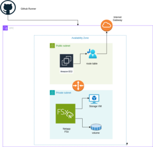
The diagram above illustrates the architecture for deploying an FSx for NetApp ONTAP file system within a single Availability Zone. The setup includes a VPC with public and private subnets, an Internet Gateway for outbound traffic, and a Security Group controlling access to the FSx file system and the EC2 instance. The EC2 instance is configured to mount the FSx volume using NFS, enabling seamless access to storage.
Setting up Pulumi
Follow these steps to set up Pulumi and integrate it with AWS:
Install Pulumi: Begin by installing Pulumi using the following command:
curl -fsSL https://get.pulumi.com | shInstall AWS CLI: If you haven’t installed it yet, install the AWS CLI to manage AWS services:
pip install awscliConfigure AWS CLI: Configure the AWS CLI with your credentials:
aws configureCreate a New Pulumi Project: Initialize a new Pulumi project with AWS and Python:
pulumi new aws-pythonConfigure Your Pulumi Stack: Set the AWS region for your Pulumi stack:
pulumi config set aws:region eu-central-1Deploy Your Stack: Deploy your infrastructure using Pulumi:
pulumi preview ; pulumi upExample: VPC, Subnets, and FSx for NetApp ONTAP
Let’s dive into an example Pulumi project that sets up a Virtual Private Cloud (VPC), subnets, a security group, an Amazon FSx for NetApp ONTAP file system, and an EC2 instance.
Pulumi Code Example: VPC, Subnets, and FSx for NetApp ONTAP
The first step is to define all the parameters required to set up the infrastructure. You can use the following example to configure these parameters as specified in the pulumi.dev.yaml file.
This pulumi.dev.yaml file contains configuration settings for a Pulumi project. It specifies various parameters for the deployment environment, including the AWS region, availability zones, and key name. It also defines CIDR blocks for subnets. These settings are used to configure and deploy cloud infrastructure resources in the specified AWS region.
config:
  aws:region: eu-central-1
  demo:availabilityZone: eu-central-1a
  demo:keyName: XYZ
  demo:subnet1CIDER: 10.0.3.0/24
  demo:subnet2CIDER: 10.0.4.0/24
The following code snippet should be placed in the infra.py file. It details the setup of the VPC, subnets, security group, and FSx for NetApp ONTAP file system. Each step in the code is explained through inline comments.
import pulumi
import pulumi_aws as aws
import pulumi_command as command
import os

# Retrieve configuration values from Pulumi configuration files
aws_config = pulumi.Config("aws")
region = aws_config.require("region")  # The AWS region where resources will be deployed

demo_config = pulumi.Config("demo")
availability_zone = demo_config.require("availabilityZone")  # Availability Zone for the deployment
subnet1_cidr = demo_config.require("subnet1CIDER")  # CIDR block for the public subnet
subnet2_cidr = demo_config.require("subnet2CIDER")  # CIDR block for the private subnet
key_name = demo_config.require("keyName")  # Name of the SSH key pair for EC2 instance access# Create a new VPC with DNS support enabled
vpc = aws.ec2.Vpc(
    "fsxVpc",
    cidr_block="10.0.0.0/16",  # VPC CIDR block
    enable_dns_support=True,    # Enable DNS support in the VPC
    enable_dns_hostnames=True   # Enable DNS hostnames in the VPC
)

# Create an Internet Gateway to allow internet access from the VPC
internet_gateway = aws.ec2.InternetGateway(
    "vpcInternetGateway",
    vpc_id=vpc.id  # Attach the Internet Gateway to the VPC
)

# Create a public route table for routing internet traffic via the Internet Gateway
public_route_table = aws.ec2.RouteTable(
    "publicRouteTable",
    vpc_id=vpc.id,
    routes=[aws.ec2.RouteTableRouteArgs(
        cidr_block="0.0.0.0/0",  # Route all traffic (0.0.0.0/0) to the Internet Gateway
        gateway_id=internet_gateway.id
    )]
)

# Create a single public subnet in the specified Availability Zone
public_subnet = aws.ec2.Subnet(
    "publicSubnet",
    vpc_id=vpc.id,
    cidr_block=subnet1_cidr,  # CIDR block for the public subnet
    availability_zone=availability_zone,  # The specified Availability Zone
    map_public_ip_on_launch=True  # Assign public IPs to instances launched in this subnet
)

# Create a single private subnet in the same Availability Zone
private_subnet = aws.ec2.Subnet(
    "privateSubnet",
    vpc_id=vpc.id,
    cidr_block=subnet2_cidr,  # CIDR block for the private subnet
    availability_zone=availability_zone  # The same Availability Zone
)

# Associate the public subnet with the public route table to enable internet access
public_route_table_association = aws.ec2.RouteTableAssociation(
    "publicRouteTableAssociation",
    subnet_id=public_subnet.id,
    route_table_id=public_route_table.id
)

# Create a security group to control inbound and outbound traffic for the FSx file system
security_group = aws.ec2.SecurityGroup(
    "fsxSecurityGroup",
    vpc_id=vpc.id,
    description="Allow NFS traffic",  # Description of the security group
    ingress=[
        aws.ec2.SecurityGroupIngressArgs(
            protocol="tcp",
            from_port=2049,  # NFS protocol port
            to_port=2049,
            cidr_blocks=["0.0.0.0/0"]  # Allow NFS traffic from anywhere
        ),
        aws.ec2.SecurityGroupIngressArgs(
            protocol="tcp",
            from_port=111,  # RPCBind port for NFS
            to_port=111,
            cidr_blocks=["0.0.0.0/0"]  # Allow RPCBind traffic from anywhere
        ),
        aws.ec2.SecurityGroupIngressArgs(
            protocol="udp",
            from_port=111,  # RPCBind port for NFS over UDP
            to_port=111,
            cidr_blocks=["0.0.0.0/0"]  # Allow RPCBind traffic over UDP from anywhere
        ),
        aws.ec2.SecurityGroupIngressArgs(
            protocol="tcp",
            from_port=22,  # SSH port for EC2 instance access
            to_port=22,
            cidr_blocks=["0.0.0.0/0"]  # Allow SSH traffic from anywhere
        )
    ],
    egress=[
        aws.ec2.SecurityGroupEgressArgs(
            protocol="-1",  # Allow all outbound traffic
            from_port=0,
            to_port=0,
            cidr_blocks=["0.0.0.0/0"]  # Allow all outbound traffic to anywhere
        )
    ]
)

# Create the FSx for NetApp ONTAP file system in the private subnet
file_system = aws.fsx.OntapFileSystem(
    "fsxFileSystem",
    subnet_ids=[private_subnet.id],  # Deploy the FSx file system in the private subnet
    preferred_subnet_id=private_subnet.id,  # Preferred subnet for the FSx file system
    security_group_ids=[security_group.id],  # Attach the security group to the FSx file system
    deployment_type="SINGLE_AZ_1",  # Single Availability Zone deployment
    throughput_capacity=128,  # Throughput capacity in MB/s
    storage_capacity=1024  # Storage capacity in GB
)

# Create a Storage Virtual Machine (SVM) within the FSx file system
storage_virtual_machine = aws.fsx.OntapStorageVirtualMachine(
    "storageVirtualMachine",
    file_system_id=file_system.id,  # Associate the SVM with the FSx file system
    name="svm1",  # Name of the SVM
    root_volume_security_style="UNIX"  # Security style for the root volume
)

# Create a volume within the Storage Virtual Machine (SVM)
volume = aws.fsx.OntapVolume(
    "fsxVolume",
    storage_virtual_machine_id=storage_virtual_machine.id,  # Associate the volume with the SVM
    name="vol1",  # Name of the volume
    junction_path="/vol1",  # Junction path for mounting
    size_in_megabytes=10240,  # Size of the volume in MB
    storage_efficiency_enabled=True,  # Enable storage efficiency features
    tiering_policy=aws.fsx.OntapVolumeTieringPolicyArgs(
        name="SNAPSHOT_ONLY"  # Tiering policy for the volume
    ),
    security_style="UNIX"  # Security style for the volume
)

# Extract the DNS name from the list of SVM endpoints
dns_name = storage_virtual_machine.endpoints.apply(lambda e: e[0]['nfs'][0]['dns_name'])

# Get the latest Amazon Linux 2 AMI for the EC2 instance
ami = aws.ec2.get_ami(
    most_recent=True,
    owners=["amazon"],
    filters=[{"name": "name", "values": ["amzn2-ami-hvm-*-x86_64-gp2"]}]  # Filter for Amazon Linux 2 AMI
)

# Create an EC2 instance in the public subnet
ec2_instance = aws.ec2.Instance(
    "fsxEc2Instance",
    instance_type="t3.micro",  # Instance type for the EC2 instance
    vpc_security_group_ids=[security_group.id],  # Attach the security group to the EC2 instance
    subnet_id=public_subnet.id,  # Deploy the EC2 instance in the public subnet
    ami=ami.id,  # Use the latest Amazon Linux 2 AMI
    key_name=key_name,  # SSH key pair for accessing the EC2 instance
    tags={"Name": "FSx EC2 Instance"}  # Tag for the EC2 instance
)

# User data script to install NFS client and mount the FSx volume on the EC2 instance
user_data_script = dns_name.apply(lambda dns: f"""#!/bin/bash
sudo yum update -y
sudo yum install -y nfs-utils
sudo mkdir -p /mnt/fsx
if ! mountpoint -q /mnt/fsx; then
sudo mount -t nfs {dns}:/vol1 /mnt/fsx
fi
""")

# Retrieve the private key for SSH access from environment variables while running with Github Actions
private_key_content = os.getenv("PRIVATE_KEY")
print(private_key_content)

# Ensure the FSx file system is available before executing the script on the EC2 instance
pulumi.Output.all(file_system.id, ec2_instance.public_ip).apply(lambda args: command.remote.Command(
    "mountFsxFileSystem",
    connection=command.remote.ConnectionArgs(
        host=args[1],
        user="ec2-user",
        private_key=private_key_content
    ),
    create=user_data_script,
    opts=pulumi.ResourceOptions(depends_on=[volume])
))
Pytest with Pulumi
# Importing necessary libraries
import pulumi
import pulumi_aws as aws
from typing import Any, Dict, List

# Setting up configuration values for AWS region and various parameters
pulumi.runtime.set_config('aws:region', 'eu-central-1')
pulumi.runtime.set_config('demo:availabilityZone1', 'eu-central-1a')
pulumi.runtime.set_config('demo:availabilityZone2', 'eu-central-1b')
pulumi.runtime.set_config('demo:subnet1CIDER', '10.0.3.0/24')
pulumi.runtime.set_config('demo:subnet2CIDER', '10.0.4.0/24')
pulumi.runtime.set_config('demo:keyName', 'XYZ') - Change based on your own key

# Creating a class MyMocks to mock Pulumi's resources for testing
class MyMocks(pulumi.runtime.Mocks):
    def new_resource(self, args: pulumi.runtime.MockResourceArgs) -> List[Any]:
        # Initialize outputs with the resource's inputs
        outputs = args.inputs

        # Mocking specific resources based on their type
        if args.typ == "aws:ec2/instance:Instance":
            # Mocking an EC2 instance with some default values
            outputs = {
                **args.inputs,  # Start with the given inputs
                "ami": "ami-0eb1f3cdeeb8eed2a",  # Mock AMI ID
                "availability_zone": "eu-central-1a",  # Mock availability zone
                "publicIp": "203.0.113.12",  # Mock public IP
                "publicDns": "ec2-203-0-113-12.compute-1.amazonaws.com",  # Mock public DNS
                "user_data": "mock user data script",  # Mock user data
                "tags": {"Name": "test"}  # Mock tags
            }
        elif args.typ == "aws:ec2/securityGroup:SecurityGroup":
            # Mocking a Security Group with default ingress rules
            outputs = {
                **args.inputs,
                "ingress": [
                    {"from_port": 80, "cidr_blocks": ["0.0.0.0/0"]},  # Allow HTTP traffic from anywhere
                    {"from_port": 22, "cidr_blocks": ["192.168.0.0/16"]}  # Allow SSH traffic from a specific CIDR block
                ]
            }

        # Returning a mocked resource ID and the output values
        return [args.name + '_id', outputs]

    def call(self, args: pulumi.runtime.MockCallArgs) -> Dict[str, Any]:
        # Mocking a call to get an AMI
        if args.token == "aws:ec2/getAmi:getAmi":
            return {
                "architecture": "x86_64",  # Mock architecture
                "id": "ami-0eb1f3cdeeb8eed2a",  # Mock AMI ID
            }

        # Return an empty dictionary if no specific mock is needed
        return {}

# Setting the custom mocks for Pulumi
pulumi.runtime.set_mocks(MyMocks())

# Import the infrastructure to be tested
import infra

# Define a test function to validate the AMI ID of the EC2 instance
@pulumi.runtime.test
def test_instance_ami():
    def check_ami(ami_id: str) -> None:
        print(f"AMI ID received: {ami_id}")
        # Assertion to ensure the AMI ID is the expected one
        assert ami_id == "ami-0eb1f3cdeeb8eed2a", 'EC2 instance must have the correct AMI ID'

    # Running the test to check the AMI ID
    pulumi.runtime.run_in_stack(lambda: infra.ec2_instance.ami.apply(check_ami))

# Define a test function to validate the availability zone of the EC2 instance
@pulumi.runtime.test
def test_instance_az():
    def check_az(availability_zone: str) -> None:
        print(f"Availability Zone received: {availability_zone}")
        # Assertion to ensure the instance is in the correct availability zone
        assert availability_zone == "eu-central-1a", 'EC2 instance must be in the correct availability zone'

    # Running the test to check the availability zone
    pulumi.runtime.run_in_stack(lambda: infra.ec2_instance.availability_zone.apply(check_az))

# Define a test function to validate the tags of the EC2 instance
@pulumi.runtime.test
def test_instance_tags():
    def check_tags(tags: Dict[str, Any]) -> None:
        print(f"Tags received: {tags}")
        # Assertions to ensure the instance has tags and a 'Name' tag
        assert tags, 'EC2 instance must have tags'
        assert 'Name' in tags, 'EC2 instance must have a Name tag'

    # Running the test to check the tags
    pulumi.runtime.run_in_stack(lambda: infra.ec2_instance.tags.apply(check_tags))

# Define a test function to validate the user data script of the EC2 instance
@pulumi.runtime.test
def test_instance_userdata():
    def check_user_data(user_data_script: str) -> None:
        print(f"User data received: {user_data_script}")
        # Assertion to ensure the instance has user data configured
        assert user_data_script is not None, 'EC2 instance must have user_data_script configured'

    # Running the test to check the user data script
    pulumi.runtime.run_in_stack(lambda: infra.ec2_instance.user_data.apply(check_user_data))
Github Actions
Introduction
GitHub Actions is a powerful automation tool integrated within GitHub, enabling developers to automate their workflows, including testing, building, and deploying code. Pulumi, on the other hand, is an Infrastructure as Code (IaC) tool that allows you to manage cloud resources using familiar programming languages. In this post, we’ll explore why you should use GitHub Actions and its specific purpose when combined with Pulumi.
Why Use GitHub Actions and Its Importance
GitHub Actions is a powerful tool for automating workflows within your GitHub repository, offering several key benefits, especially when combined with Pulumi:
- Integrated CI/CD: GitHub Actions seamlessly integrates Continuous Integration and Continuous Deployment (CI/CD) directly into your GitHub repository. This automation enhances consistency in testing, building, and deploying code, reducing the risk of manual errors.
- Custom Workflows: It allows you to create custom workflows for different stages of your software development lifecycle, such as code linting, running unit tests, or managing complex deployment processes. This flexibility ensures your automation aligns with your specific needs.
- Event-Driven Automation: You can trigger GitHub Actions with events like pushes, pull requests, or issue creation. This event-driven approach ensures that tasks are automated precisely when needed, streamlining your workflow.
- Reusable Code: GitHub Actions supports reusable “actions” that can be shared across multiple workflows or repositories. This promotes code reuse and maintains consistency in automation processes.
- Built-in Marketplace: The GitHub Marketplace offers a wide range of pre-built actions from the community, making it easy to integrate third-party services or implement common tasks without writing custom code.
- Enhanced Collaboration: By using GitHub’s pull request and review workflows, teams can discuss and approve changes before deployment. This process reduces risks and improves collaboration on infrastructure changes.
- Automated Deployment: GitHub Actions automates the deployment of infrastructure code, using Pulumi to apply changes. This automation reduces the risk of manual errors and ensures a consistent deployment process.
- Testing: Running tests before deploying with GitHub Actions helps confirm that your infrastructure code works correctly, catching potential issues early and ensuring stability.
- Configuration Management: It manages and sets up necessary configurations for Pulumi and AWS, ensuring your environment is correctly configured for deployments.
- Preview and Apply Changes: GitHub Actions allows you to preview changes before applying them, helping you understand the impact of modifications and minimizing the risk of unintended changes.
- Cleanup: You can optionally destroy the stack after testing or deployment, helping control costs and maintain a clean environment.
Execution
To execute the GitHub Actions workflow:
- Placement: Save the workflow YAML file in your repository’s .github/workflows directory. This setup ensures that GitHub Actions will automatically detect and execute the workflow whenever there’s a push to the main branch of your repository.
- Workflow Actions: The workflow file performs several critical actions:
- Environment Setup: Configures the necessary environment for running the workflow.
- Dependency Installation: Installs the required dependencies, including Pulumi CLI and other Python packages.
- Testing: Runs your tests to verify that your infrastructure code functions as expected.
- Preview and Apply Changes: Uses Pulumi to preview and apply any changes to your infrastructure.
- Cleanup: Optionally destroys the stack after tests or deployment to manage costs and maintain a clean environment.
By incorporating this workflow, you ensure that your Pulumi infrastructure is continuously integrated and deployed with proper validation, significantly improving the reliability and efficiency of your infrastructure management process.
Example: Deploy infrastructure with Pulumi
name: Pulumi Deployment

on:
  push:
    branches:
      - main

env:
  # Environment variables for AWS credentials and private key.
  AWS_ACCESS_KEY_ID: ${{ secrets.AWS_ACCESS_KEY_ID }}
  AWS_SECRET_ACCESS_KEY: ${{ secrets.AWS_SECRET_ACCESS_KEY }}
  AWS_DEFAULT_REGION: ${{ secrets.AWS_DEFAULT_REGION }}
  PRIVATE_KEY: ${{ secrets.PRIVATE_KEY }}

jobs:
  pulumi-deploy:
    runs-on: ubuntu-latest
    environment: dev

    steps:
      - name: Checkout code
        uses: actions/checkout@v3
        # Check out the repository code to the runner.

      - name: Configure AWS credentials
        uses: aws-actions/configure-aws-credentials@v3
        with:
          aws-access-key-id: ${{ secrets.AWS_ACCESS_KEY_ID }}
          aws-secret-access-key: ${{ secrets.AWS_SECRET_ACCESS_KEY }}
          aws-region: eu-central-1
        # Set up AWS credentials for use in subsequent actions.

      - name: Set up SSH key
        run: |
          mkdir -p ~/.ssh
          echo "${{ secrets.SSH_PRIVATE_KEY }}" > ~/.ssh/XYZ.pem
          chmod 600 ~/.ssh/XYZ.pem
        # Create an SSH directory, add the private SSH key, and set permissions.

      - name: Set up Python
        uses: actions/setup-python@v4
        with:
          python-version: '3.9'
        # Set up Python 3.9 environment for running Python-based tasks.

      - name: Set up Node.js
        uses: actions/setup-node@v3
        with:
          node-version: '14'
        # Set up Node.js 14 environment for running Node.js-based tasks.

      - name: Install project dependencies
        run: npm install
        working-directory: .
        # Install Node.js project dependencies specified in `package.json`.

      - name: Install Pulumi
        run: npm install -g pulumi
        # Install the Pulumi CLI globally.

      - name: Install dependencies
        run: |
          python -m pip install --upgrade pip
          pip install -r requirements.txt
        working-directory: .
        # Upgrade pip and install Python dependencies from `requirements.txt`.

      - name: Login to Pulumi
        run: pulumi login
        env:
          PULUMI_ACCESS_TOKEN: ${{ secrets.PULUMI_ACCESS_TOKEN }}
        # Log in to Pulumi using the access token stored in secrets.

      - name: Set Pulumi configuration for tests
        run: pulumi config set aws:region eu-central-1 --stack dev
        # Set Pulumi configuration to specify AWS region for the `dev` stack.

      - name: Pulumi stack select
        run: pulumi stack select dev
        working-directory: .
        # Select the `dev` stack for Pulumi operations.

      - name: Run tests
        run: |
          pulumi config set aws:region eu-central-1
          pytest
        working-directory: .
        # Set AWS region configuration and run tests using pytest.

      - name: Preview Pulumi changes
        run: pulumi preview --stack dev
        working-directory: .
        # Preview the changes that Pulumi will apply to the `dev` stack.

      - name: Update Pulumi stack
        run: pulumi up --yes --stack dev
        working-directory: .
        # Apply the changes to the `dev` stack with Pulumi.

      - name: Pulumi stack output
        run: pulumi stack output
        working-directory: .
        # Retrieve and display outputs from the Pulumi stack.

      - name: Cleanup Pulumi stack
        run: pulumi destroy --yes --stack dev
        working-directory: .
        # Destroy the `dev` stack to clean up resources.

      - name: Pulumi stack output (after destroy)
        run: pulumi stack output
        working-directory: .
        # Retrieve and display outputs from the Pulumi stack after destruction.

      - name: Logout from Pulumi
        run: pulumi logout
        # Log out from the Pulumi session.